Everyone has been working on converter clutches for years. In this day and age there several different styles of converter clutches, captive clutch, multi-disk clutches (think clutch drums). 2 passage and 3 passage hydraulic systems. These systems all have their own issues.
 In this edition of Fun With Transmissions, we’ll check out the Honda Odyssey 6-speed (PYRA) with torque converter clutch shudder concerns by using scan tool data and then looking at the converter’s internal function and valve body operation. Keep in mind that you can apply the approach we’ll go through to other models with a torque converter clutch and speed sensors.
First Things First
The 2014 to 2017 Odyssey models have a common complaint of a shudder (or judder as Honda describes it) between 20 and 60 mph. It occurs under light to moderate throttle and is most noticeable when tipping into the throttle after braking.

According to Honda TSB number 17-043, the manufacturer says a fluid change and a reflash of the controller may work. Here are the highlights from the Honda factory bulletin:
After the software update, some vehicles, based on how they are driven (extreme conditions), may still experience a judder complaint due to ATF deterioration, and the judder may return. The problem is typically diagnosed as a bad torque converter. There is no damage to the torque converter, but because the ATF has deteriorated, it needs to be changed even though the “ATF Service Due” message has not appeared.

 Further along in the factory information, it talks about flushing the unit three times! So, in general, a vehicle coming into a dealership under warranty got a transmission fluid service and updated PCM programming.
The Honda factory powertrain warranty at 60,000 miles gives us a checkpoint to consider when a vehicle comes into our shop. If you have a scan tool that can access the program part number, look for part number 37806- RV0-5070 or later to verify the PCM has been updated.
You may recommend this as a possible solution if the service has not been performed. Be sure to let the customer know that it MAY solve the issue, but if not, the transmission would need to be removed!
 What’s going on in there?

Using our scan tool, we will identify and isolate the critical parameters to view the judder as it happens in realtime. That is to say, we can record the judder happening and return to the shop where we can safely watch the event happen. Note that when there are fewer parameters that the scan tool displays, the update rate is faster, and the accuracy is much better.
The critical parameters are:
- Engine speed (rpm)
- Throttle Position Sensor (TPS)
- Input Shaft (Mainshaft) Speed (rpm)
- Output Shaft (CounterShaft) Speed (rpm)
- Shift Control
Earlier, we discussed that these are Honda-specific terms; however, we can relate these terms and input readings to all electronically controlled transmissions and TCC systems.
 All quality scan tools will have engine speed data in RPMs. They will also show TPS data. On vehicles that are not Honda, there will be an Input Speed Sensor (ISS) and Output Speed Sensor (OSS). Lastly, the “shift control” parameter may be displayed as “gear command.” These are the most important parameters when looking at TCC judder or TCC-related issues. Once the selected parameters are isolated, set the scan tool to graphing mode. It is much easier to see the fluctuations in the readings when viewed in graphing mode.
How do we know what’s bad and what’s good?
It is a good idea to take the scan tool on that final road test to get a known good recording for comparison with a car with an issue. I know we are busy in our work-a-day world, so why would we want to take the time to graph a vehicle that works well? Everyone knows we’re working to get cars delivered so we can get paid, right?
 In figure one, we have a graph from a known, good working Odyssey. It shows the engine rpm (red line), the input shaft speed (lavender line), and the output shaft speed (green line). We can also see the smooth rise of the TPS when accelerating and the shift commands are occurring correctly.
Now compare that to a vehicle with a judder complaint (figure 2). We can clearly see the judder happening. The input shaft signal (lavender line) shows the judder sensation in the form of a squiggly line. You can also see it in the output shaft sensor signal (green line). Using the scan tool this way allows us to see the problem at the same time that we feel it.
Where is the problem?
 Now that we have seen the problem on the scan tool, flushed the transmission with copious amounts of clean ATF, and updated the PCM, what if this doesn’t cure the problem? Well, it’s time to remove the unit and at least replace the torque converter and, depending on the unit’s mileage, perhaps an internal inspection.
Let’s look inside the torque converter to see where the issue is. At the heart of the converter is the converter clutch assembly. The Honda Odyssey converter has a clutch drum that’s part of the front cover (figure 3). Many manufacturers use this arrangement; others, including Honda, also use the single piston with clutch material bonded to it (figure 4).
The fluid flush may not affect the judder because the piston seals are getting hard and not sealing as designed. In this case, the only fix is removing the converter, changing the piston seals on the converter clutch apply piston (figure 5), and renewing the friction and steel plates as needed.
How the TCC is controlled?
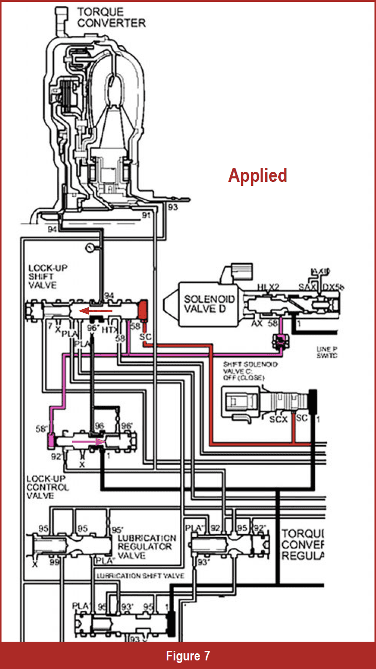 We checked out the judder diagnosis, looked into the torque converter, and now we’ll examine how the TCC is controlled. Like many other transmissions, the Honda 6-speed TCC operation is controlled by two solenoids. The controller switches on one solenoid to enable lock up (Shift Solenoid C) and one pulse width solenoid to control the rate of TCC apply (Pressure Control Solenoid D). When the controller commands lockup, the C solenoid is switched on. The valves are moved into the lock-up position. Next, the controller modulates the Pressure Control Solenoid D on, gradually applying the TCC. The gradual application makes for a smooth engagement.
The Honda unit can command lock up in all forward ranges. Figure six shows the valve body in the TCC off position. Figure seven shows the valve body in the ON position.
Lock-up problems can be a real pain, but when we know how it works and what is involved, we can make informed decisions and have more Fun With Transmissions!