Since Chrysler introduced the A604 transmission in 1989, controlling the power feed to the transmission was a major concern. Low resistance, fast acting pulse width modulated solenoid circuits needed to be monitored and tested constantly to ensure the computer would not be damaged. When shorts to power, shorts to ground and open circuit faults are detected, the PCM is programmed to immediately cut control power to the transmission, placing it in fail safe mode.
This type of circuit control is used in all front wheel drive applications starting with the A604 (40TE), and rear wheel drive applications starting with the 42-47RE series units. In the mid-2000’s, Chrysler moved the transmission control circuitry and built it into the fuse box (Integrated Power Module or IPM). The Transmission Control Relay appeared in place of the Electronic Automatic Transaxle (EATX) relay.
 Later models use the PCM Control Relay or the Auto Shut-Down (ASD) relay to control transmission power. A microprocessor was added, and circuit boards replaced bulky wiring and connectors inside. What was formerly known as the IPM was renamed the Totally Integrated Power Module or TIPM (pronounced tip-um). Since this component is essential to our transmission, let’s take a closer look at how it works and why it fails.
Transmission Control Circuit Overview
The TIPM was engineered to modularize the fuse box by decreasing wiring complexity and weight. To achieve this goal, several relays were incorporated into the circuit board. The Transmission Control Relay was one of the relays affected. Depending on the vehicle year and model, it may or may not be serviceable.
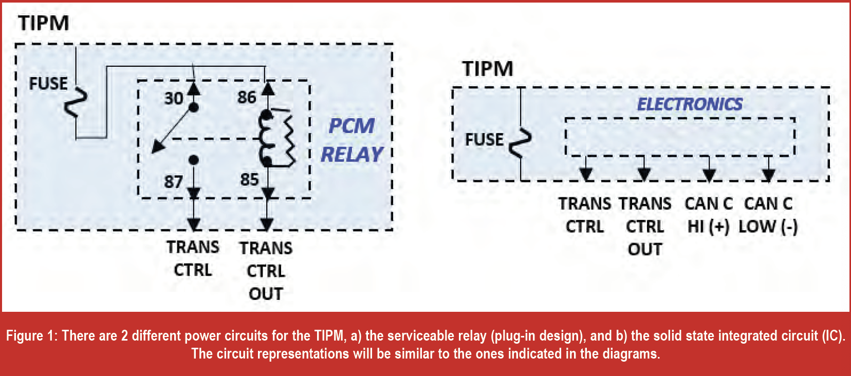
There are two different designs: a remote relay circuit or a solid state integrated circuit. The remote relay design may be a serviceable relay plugged into the fuse box, or mounted in the engine compartment. You’ll need to access the wiring diagram for your specific year, make and model vehicle to know which design you have (figure 1).
All Chrysler transmission power control systems have the same basic functional characteristics. Whether relay controlled or solid state IC controlled, a control signal is produced by the PCM/TCM called Transmission Control (figure 2). This is a low current power or ground signal. When the vehicle is started or the ignition is switch from off to RUN, a signal is sent to the TIPM to power up the transmission. The TIPM or relay powers up the transmission through the Transmission Control Output circuit. The PCM/TCM evaluates whether to keep the power on, or cut it off by testing the Transmission Control Output circuit for faults. This happens within 1-3 seconds of powering up.
The solid state integrated circuit uses a microprocessor to directly control the high-current voltage supply for the solenoids. There is no way to test the control side of the circuit by back probing, since there is no relay. Data from a scan tool is the only way to observe what is happening there. However, you can back probe the Transmission Control and Transmission Control Output circuits.
Why Do They Fail?
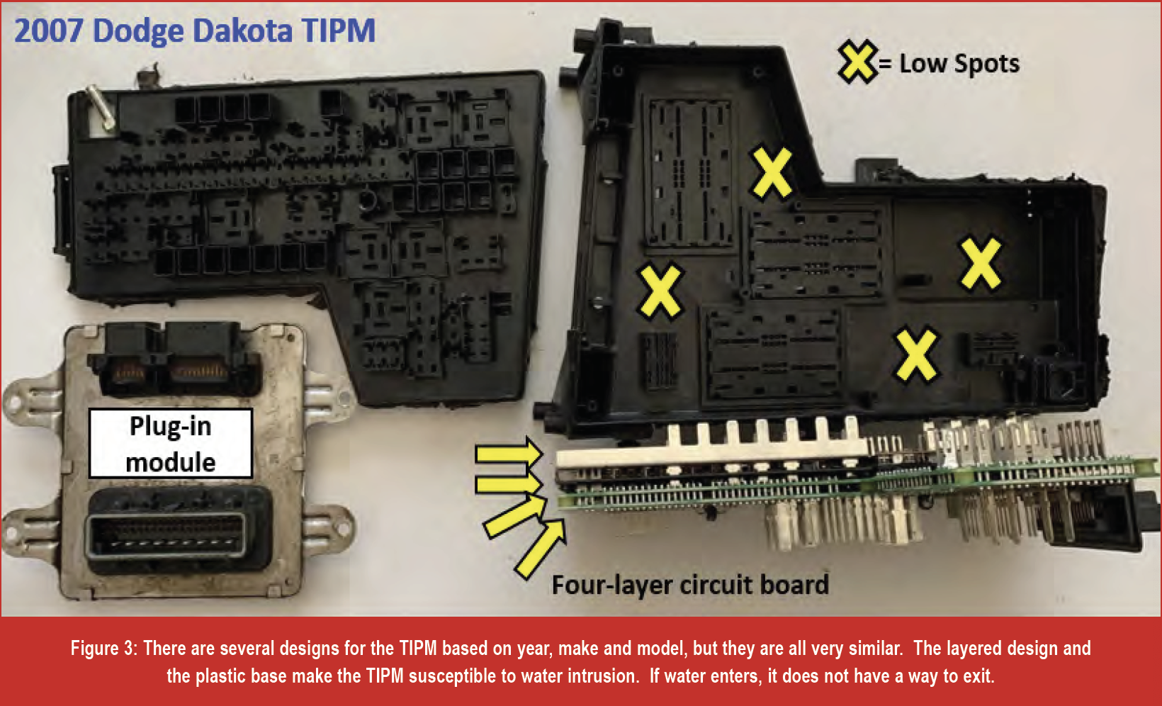
Water intrusion is a common concern with these modules (figure 3). The internal, layered design and the under hood location of these modules on different models makes them somewhat vulnerable. Normal rainy day conditions are not much of a concern, however, when there is ice build-up, snow and leaves added to the equation, then the game changes. The TIPM also makes a nice, inviting place for rodents to make a nest. Also, if the inner fender welds are missing or compromised by an accident, consistent road spray from the tires can cause moisture intrusion.
Aftermarket add-ons that are incorrectly installed are another cause for TIPM failures. The TIPM is designed to feed power and control grounds to the OEM installed components. Trailer lighting and other minor circuit additions can be handled by the module, but nothing more! Spliced connections made into existing circuits will overload the capacity of the TIPM and cause repeat failures if not addressed. Aftermarket components should have their own dedicated fused power from the battery. Relay circuits can be used to sequence circuit activation with other OEM components. Inspect aftermarket wiring for issues.
 Other factors like corroded contacts, compromised wiring and failing solenoids can cause stress to the TIPM power and ground control circuits. A weak battery or poor charging system can also cause problems. Like any computer module, prolonged unstable voltage conditions can cause the TIPM to fail.
Related Symptoms of a Failing TIPM
It seems like when cars act up and they finally end up at the shop for diagnosis, that’s the time they work correctly! TIPM related problems are no different. As a matter of fact, they tend to show intermittent issues. Since the customer’s complaint is most likely related to the transmission being stuck in 2nd gear intermittently, we may find it difficult to duplicate this. If this situation is related to a failing TIPM, we can look at other operational issues that may be present. Here are a few of the most common issues:
- The transmission is in fail safe
- The air bag light stays on with no service codes
- The engine stalling while driving
- The starter cranks but won’t start
- The fuel pump not turning on or off
- The horn going off at random times or does not work
- Power windows not working
- Doors locking or unlocking themselves
- Intermittent blower motor
- Coolant fans inoperative
- Wiper issues
- Reverse lights intermittent or not functioning
- ABS problems
- A/C Compressor does not activate
- Radio shuts off while driving
- The customer hears a buzzing sound, similar to an electrical relay partially making contact while the ignition is off.
While the presence of these issues may indicate a possible TIPM issue, always verify power and ground to the TIPM first. Always perform voltage drop testing with KOEO or KOER. Wiggle the harness and connectors while performing voltage drop tests to help locate intermittent issues.
Fixing the Problem
If your tests point to a bad TIPM, purchasing an OEM new part is one solution. Depending on the make and model of the vehicle you are working on, you may have the option of having your module repaired. However, if your module failed due to water intrusion, you will need to replace it.
TIPM modules without the solid state integrated circuit control can be repaired. In an article that appeared in the April 2018 edition of GEARS Magazine, there is a complete overview of how to bypass the TIPM for testing purposes. Note, this can be used as a permanent fix, however, the circuit modification could be disputed as inadequate if the vehicle ends up at a dealership or shop other than yours with similar concerns.
If you wish to locate a used TIPM, make sure you get the same part number. Also, be aware that you may have to go through a few modules before you end up with one that works. Remember, this component is prone to many different issues!
 Also, there are aftermarket facilities that can perform repairs on your existing TIPM. Contact them directly regarding your vehicle application and issues for possible repair.
Finalizing the Repair
Once the new TIPM is installed in the vehicle, it needs to be “learned”. One method that works frequently involves allowing the CAN system to initialize the new TIPM. One method that seems to work well, but not all the time, is to perform the following:
- Close the hood.
- Turn the ignition key to the “RUN” position for at least twelve seconds.
- After twelve seconds, turn the ignition key to the “OFF” position.
- Turn the ignition key back to the “ON” position, start the vehicle and verify proper vehicle system operation.
Of course, the PCM and the CAN bus have to be in working order for it to function properly. After this process, certain parameters may need to be individually addressed, such as:
- The tire ratio parameter.
- The anti-theft system locks out the starting signal (requires a four-digit security code from the dealer).
If you have these issues, you will need a scan tool that is capable of performing these procedures.
If this process does not work, you may need a factory scanner (or equivalent) to initialize the TIPM. A “Restore Vehicle Configuration” will be needed, which requires the VIN to be entered into the TIPM. Navigate to ECM/PCM menus to find the “Restore Vehicle Configuration” function on your scanner.
In the event that none of these processes work, you will need to access a factory scan tool to perform a “Restore Vehicle Configuration” procedure.
Problematic components can be a nuisance to diagnose, especially when you don’t know how they operate. Knowing proper operation as well as various failure modes can prove valuable when diagnosing. Knowledge is the most valuable tool that you can possess. Hopefully, you can add this information to your diagnostic tool box!