We know when we rebuild our transmissions we must take the valve bodies completely apart and make sure that all the valves fall into the bores on there on their own weight. Remember that your pocket screwdriver is NOT a valve body rebuilding tool! Do you know what all those valves do? In this edition of Fun With Transmissions we are going to revisit hydraulic fundamentals. We are going to check out the three different types of valves and we will also check out some of the newer valve bodies. Let’s get into it!
There are only three basic valves, they are:
- Regulator: A regulator valve lowers pressure from a higher‐pressure source. A regulator can have a static setting, producing a constant value of pressure; or it can vary the pressure output, based on the influences from mechanical force or hydraulic pressure.
- Switch: A switch valve works like a light switch; it’s either on or off. It supplies a component or another valve with oil, or it exhausts the oil to the sump. The most common valve of this type is a shift valve. It can direct oil to a shifting element, like a servo or clutch drum; or it can switch oil pressure between two other valves. Many PWM regulators are really switch valves that open and close so quickly they actually operate as a regulator; but the valve is still considered a switch.
- Servo: A servo valve moves another valve; either a switch valve or regulator valve.
REGULATOR VALVES
The regulator valve is the most common, but the most difficult to recognize because there are several types of regulators. There are two properties common to all regulators that will help you identify them:
- Nearly all regulators use a spring
- Source pressure is used to move the valve toward the spring.
All regulators require a balance system to maintain regulation. Most balance systems take pressure that the regulator has modified and uses it on an area of the regulator. 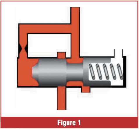 This balance pressure works on the valve to move it toward the spring.
In these examples, there are three basic regulators. In the first example, the balance oil is regulated pressure that is diverted to the end of the valve (Figure 1). The feed limit valves in a Gen 2 10L80 are a good example in today’s transmissions.
The second regulator uses an internal balance system: Pressure isn’t diverted to the end of the valve; instead, the pressure goes between two of the lands on the valve. Since the land closer to the spring is larger, the force created by hydraulic pressure pushes the valve toward the spring (Figure 2).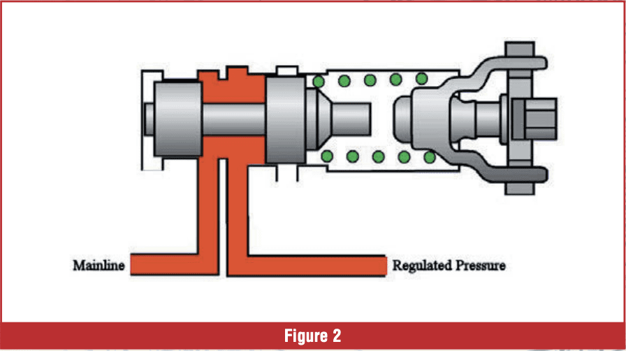
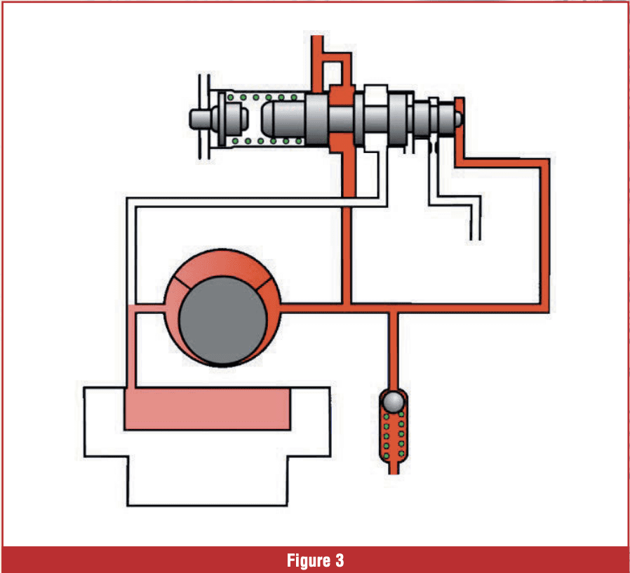
The third type of regulator is a main pressure regulator, which operates by bleeding off pressure directly from the pump feed to maintain a balanced pressure. The source pressure for the main pressure regulator originates from the pump, rather than a regulated source. These main pressure regulators use mainline pressure to provide balance pressure. This prevents the entire system from exceeding the level set for the system (Figure 3).
 SWITCH VALVES
Switch valves, as their name implies, switch oil on or off. They can direct oil to a shifting element or another valve.
Switch valves don’t vary pressure like a regulator; they’re either open or closed. Typically, when a switch valve closes a circuit, it will also open that circuit to exhaust.
There is one property of a switch valve that makes it easy to identify: A switch valve doesn’t use source pressure to move the valve. There’s always some other force that moves the valve.
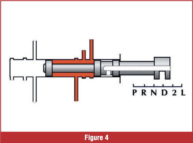 In the next two examples, there are two basic switch valves. In the first example the valve is controlled mechanically. This would be used as a manual valve or detent valve. In the second example, the switch valve is controlled by some other pressure. This arrangement is commonly used for shift valves (Figures 4 & 5).
SERVO VALVES
Servo valves serve one main purpose: To move other valves. But sometimes a manufacturer will also use a servo valve as regulator or a switch. 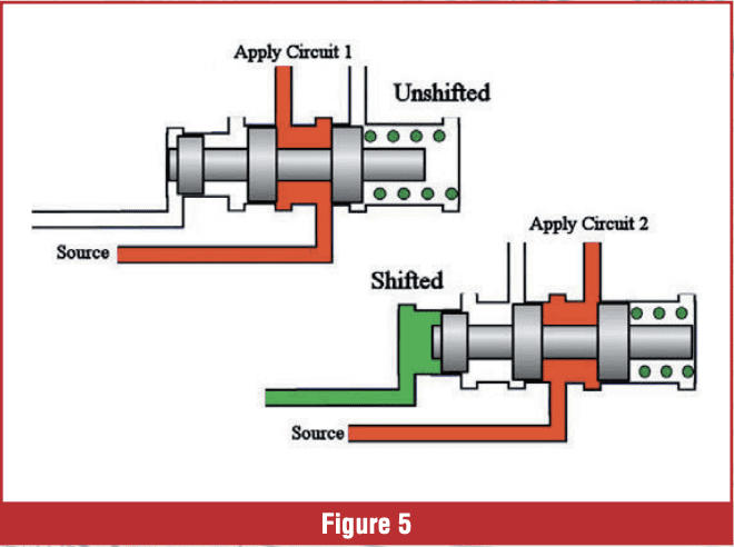 You may want to consider these combination valves. A combination valve then can be referred to as a servo/ switch valve, or a servo/regulator valve; but its primary function is a servo valve. Figure 6 shows 3 examples of servo valves.
SWITCH VALVES THAT REGULATE PRESSURE
Many units today control line pressure using a pulse width modulated solenoid. These solenoids open and close very quickly, which regulates the pressure applied to one side of a switch valve. 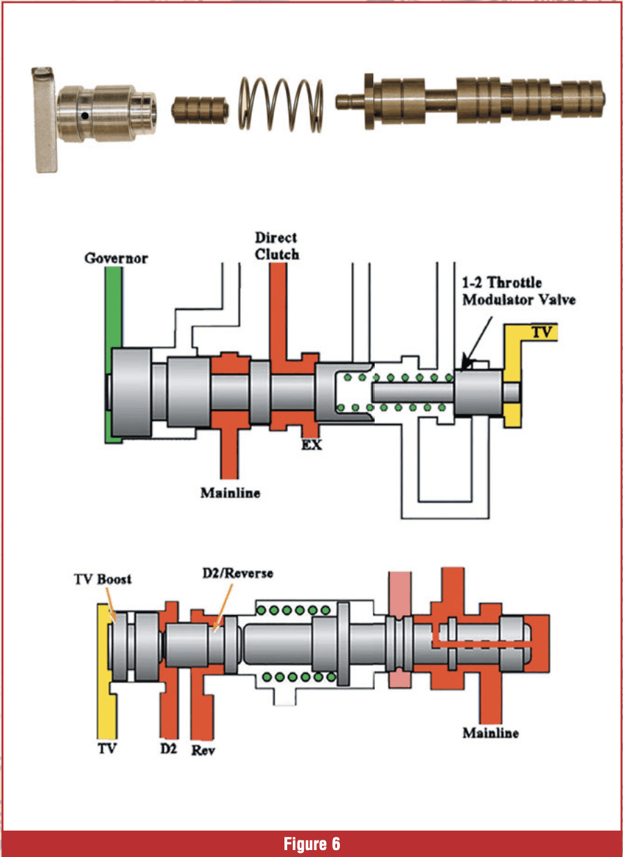 This causes the switch valve to float between wide open and full closed, regulating the pressure to the circuit. Even though these valves regulate pressure, they’re still considered switch valves.
In figure 7 the solenoid is receiving a pulsed signal. These pulses are so fast, they cause the switch valve to float between open and closed, causing the valve to work as a regulator.
SOLENOID ACCUMULATORS
We just visited the switch valves that regulate. Because there are pulses, fast pulses, in many units these days there are accumulators that are part of the solenoid/valve circuit (Figure 8). These accumulators act like shock absorbers to cushion the pulses to the valve that the solenoid is controlling. 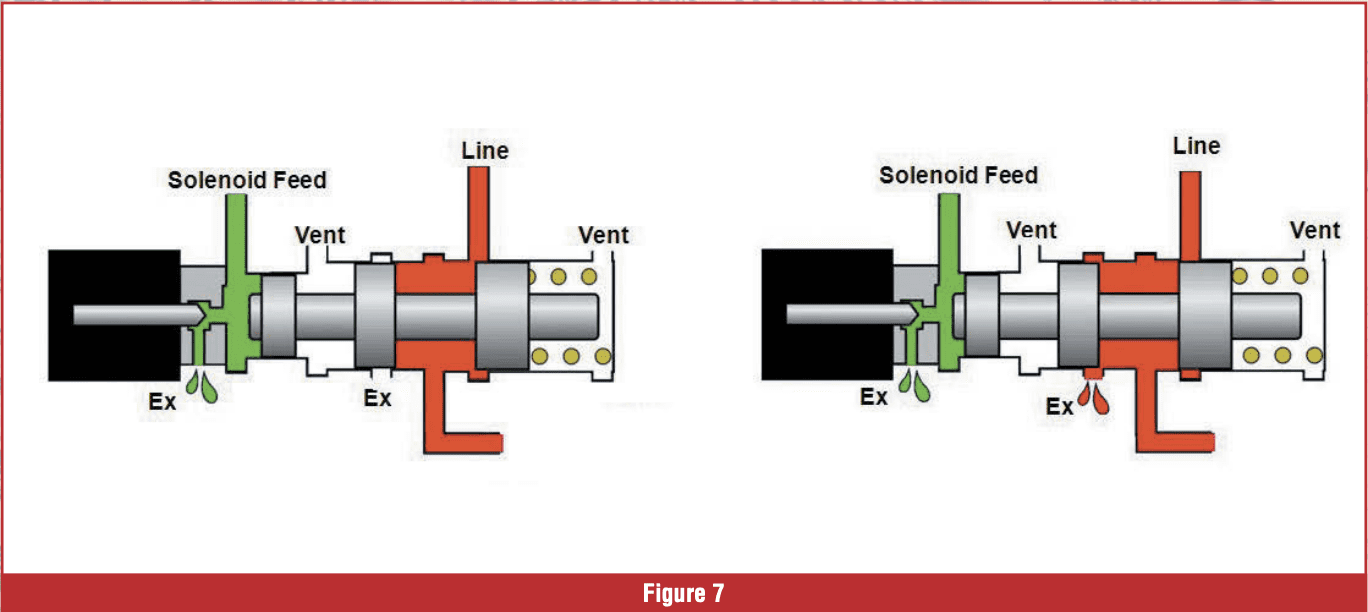 This is important to understand because these accumulators are prone to wearing out and can cause severe pressure leaks. When these leaks happen, the valves do not perform as designed and shift/ pressure control issues will happen. There are several aftermarket fixes to correct these worn castings.
ONE ODD VALVE
Lastly, we are going to check out one odd valve in the Allison 10L1000.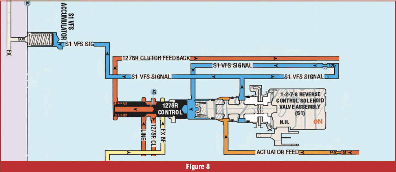
The main regulator valve on the 10L1000 is quite different than all other pressure regulators in the past. The inboard spool at rest does not contact the bore on its OD (Figure 9).
There is also no balance circuit that acts on the inboard end of the valve like normal. It is simply the diameter of the larger spool that acts as the balance spool regulating pressure to the components downstream and metering a connection to the decrease circuit on the pump slide.

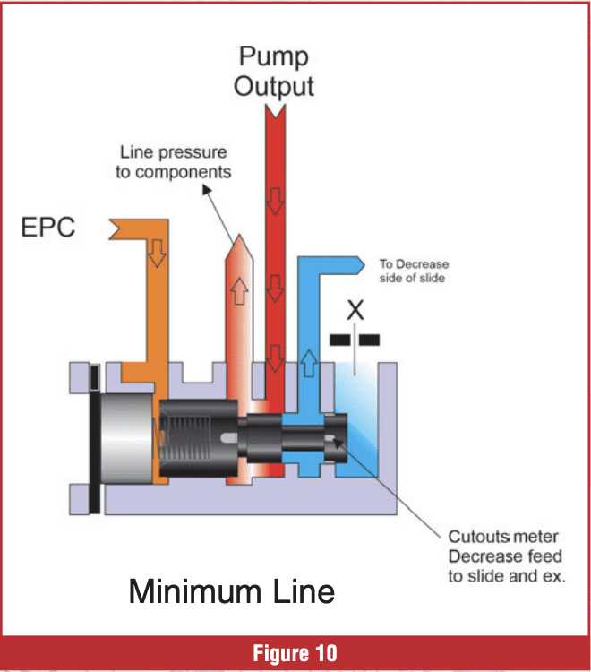
At minimum line pressure the two smaller spools regulate decrease pressure, acting on the pump slide controlling the volume from the pump (Figure 10).
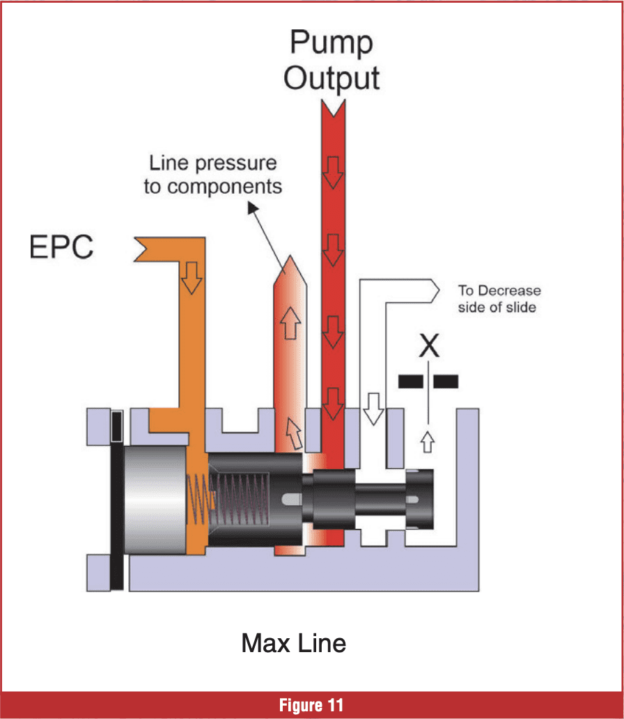
At max line pressure there is little to no connection to the decrease side of the pump slide which provides the largest pump volume (Figure 11). Thanks to Jim Dial and Sonnax for the description and graphics
VALVES WITH NO SPRINGS ATTACHED.
Since the first automatic transmissions came out (a really long time ago) valves had springs. Regulator valve, shift valves all have springs. These springs could be changed, stronger or weaker, to change pressures and shift timing. Todays 10 speed units do not have shift valve springs. There is constant pressure, called exhaust backfill pressure forcing the valve against the mechanical shift solenoids (Figure 12).  This exhaust backfill pressure is very low, typically between 5-10psi. If the pressure were any higher the solenoid would not be able to move the valve.
Knowing the types of valves is very important to understanding what we are working on when disassembling/ assembling valve bodies. When we have that better understanding it much easier having Fun With Transmissions.