Solenoids have been around since the late 70s, evolving from simple on/off solenoids to pulse width modulated clutch pressure control solenoids. Now we have a new breed of solenoid on the road. In this edition of Fun With Transmissions, we will check out the Casting Integrated Direct Acting Solenoids (CIDAS). We will also be checking into how they work and how to test them.
In so many shops around the country these days, solenoids are replaced regularly because there was a failure in the past, and replacing them becomes “standard operating procedure.” While this may seem very safe, it can be expensive and time-consuming (waiting for parts).

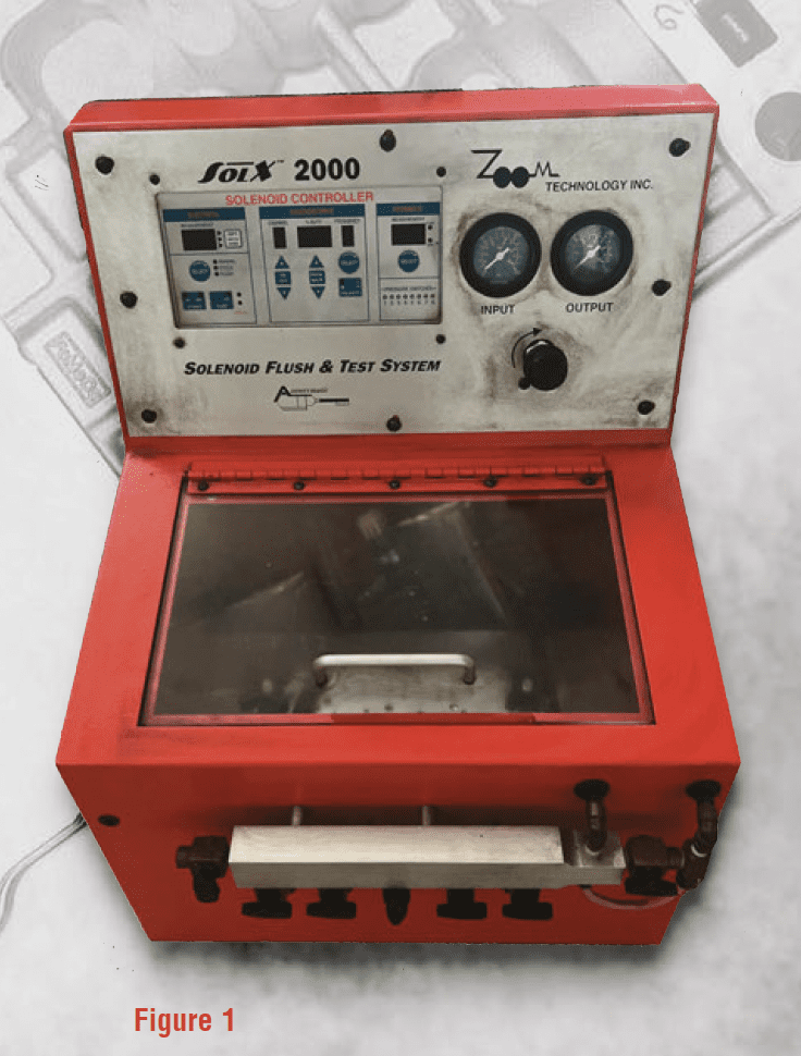 Hey, how about we test those solenoids for proper operation? That might seem like a great idea at first, but the hydraulic solenoids that have been around forever are not exactly “test friendly.” Hydraulic solenoids require a special testing machine or flow bench to do two things; energize the solenoid and pump transmission fluid through them at a measurable rate (Figure 1). The idea is that we have repeatable, measurable results to know which solenoids to use and which solenoids to trash. It’s a fact that shops that use this approach have saved a ton of money and saved themselves dreaded comebacks.
Now, regarding the new CIDAS solenoids and how we can test them. First, let’s check out how these solenoids are put together and how they function. Figure two is a hydraulic illustration of a typical CIDAS solenoid configuration.
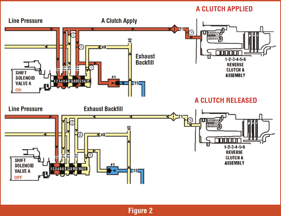
When the solenoid is powered up (figure 2, upper schematic), the pintle extends and pushes the valve to the right, opening the valve to line pressure to apply the clutch. This is a Pulse Width Modulated (PWM) solenoid, so the computer controls the clutch application time rate. When the solenoid is off (figure 2, lower schematic), the pressure on the right side of the valve pushes the valve and the pintle towards the solenoid to release the clutch.
 CONSTRUCTION

The folks that designed these solenoids got it right. The interesting feature is the carbon fiber sleeve that lines the barrel where the plunger and the pintle move during operation (Figure 3). The sleeve and the fluid interacting on the moving parts make this a durable solenoid. The solenoids are not serviceable. We have destroyed the solenoid so the industry can see what’s inside.
TESTING
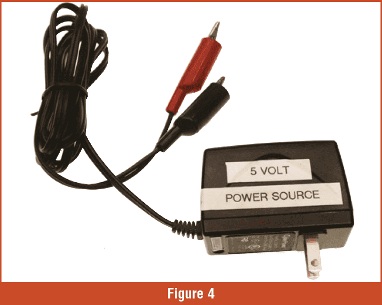
To bench-test a CIDAS solenoid, we will need a power source. There are a couple of different options here. First, the easiest method is using a 5-volt power source (Figure 4). We added alligator clips and the unit is ready to go. Keep in mind that the CIDAS solenoids check in at 5 ohms resistance, so the 5 volt source is plenty to do the job.
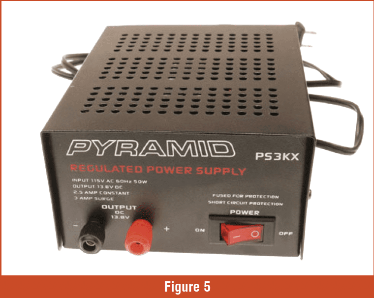
 The other option is a 12-volt power source (Figure 5). This unit comes in handy when testing other solenoids with higher resistance. Be careful with the 12-volt power source. Do not leave the solenoid hooked up for any length of time. The solenoid will get very hot!
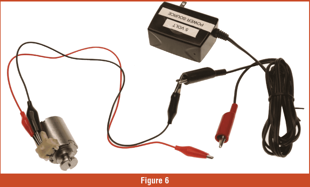
To test the solenoid, we connect the jumper wires to the solenoid, as shown in figure 6, and attach the negative lead from the power source. Now hold the solenoid down on the bench and tap the positive wire to the solenoid. Hang on! The solenoid is going to pop up very quickly. Remember the hydraulic pressure on the valve keeps pushing the plunger in at all times.
 If the solenoid fails the test and needs replacing, pay attention to the solenoid band number. The replacement solenoid must have the same number (Figure 7).
Solenoid testing is not going away, and when it’s done correctly, the process will save time and money in the long run. And we all know this is how we have Fun With Transmissions!