
This article is part three of a series that examines the limitations and considerations of common measurements performed with one of the most widely used diagnostic tools, the Digital Multimeter (DMM). In the November 2025 issue, I addressed some limitations and misuses of the voltmeter. The December 2025 issue discussed the operation, use, and misuse of the ohmmeter. This article focuses on the amperage setting, and if the average technician’s DMM is like my students’, the DMM’s ammeter fuse is likely blown!
AMMETER FUNCTION AND USAGE
Amperage is actually one of the best measurements for any load that requires a decent amount of current to operate. Most outputs are electromagnetic or lighting – think about that for a moment. The actuators and devices on a vehicle either emit light or operate using a magnetic field. Components such as motors, coils, relays, solenoids, injectors, and speakers all operate using the principles of electromagnetism. These electromagnetic devices require a specific level of power to work properly. A unit of power is the Watt, which is calculated as volts multiplied by amps (P = V · A). To get a good understanding of a circuit, measuring voltage and current can indicate whether it is operating as intended. With that said, amperage is the least likely measurement to be found published in a service manual. As described in the DMM Series Parts One and Two, resistance measurements are very common, and voltage is fairly common as well. Between those two, a technician can do a good job of validating a circuit, but there are times when monitoring the actual amperage might come in handy. For example, if you have an electric motor that has high mechanical resistance. The voltage will measure out fine, and electrical resistance testing with a DMM on the motor is mostly pointless unless the tech is looking for an open or short to ground. In these cases, measuring the amperage with a meter would provide clues to the mechanical failure (high current). But for most DMM-based diagnostics, the ammeter is not a common go-to tool.

METER OPERATION
When the DMM is set to amps, the meter passes full circuit current. This is why the ammeter must be placed in series with the circuit. This is also why many ammeters blow fuses. Either a technician checks a circuit that’s pulling too much current, or they unknowingly measure a circuit in parallel with the load, allowing current to bypass the load, unregulated. 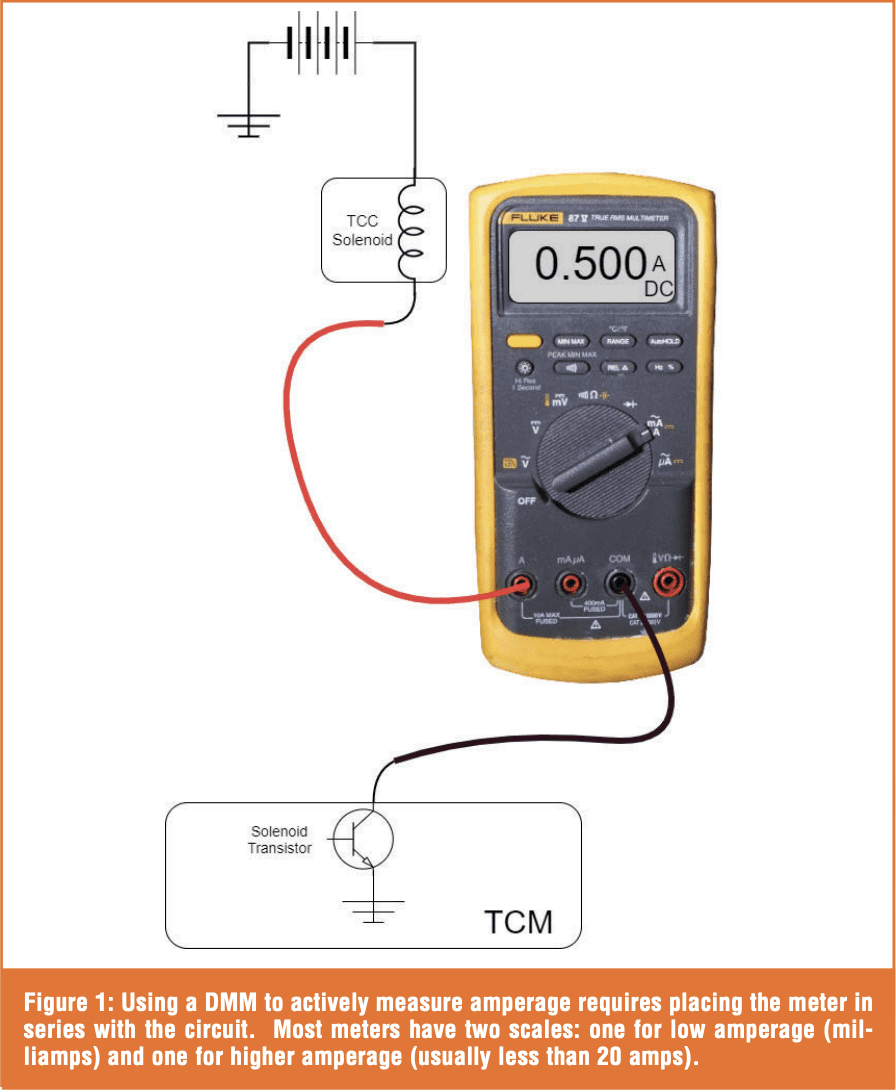 Figure 1 shows the proper connection of a DMM when actively checking amperage. The meter essentially becomes part of the circuit. On a simple series circuit, as shown, the current is the same throughout, so it doesn’t matter where the series connection is made.
During this direct amperage measurement, the meter internally measures the voltage drop across a shunt resistor located within the meter. This shunt has very low resistance, so it doesn’t affect the circuit’s operation. Figure 2 shows a milliohm meter measuring the resistance of the shunt resistor in common meters; the resistance is very low, ranging from 0.025 to 0.040 ohm. Since the meter is calibrated with the shunt resistance, when current passes through the meter, the voltage drop across the shunt allows the meter to calculate the current using Ohm’s Law. For example, internally, if the Fluke meter measures a 0.043-volt drop across the shunt and the shunt is 0.043 ohms, it calculates the amperage at 1.0 amps (V = I*R).
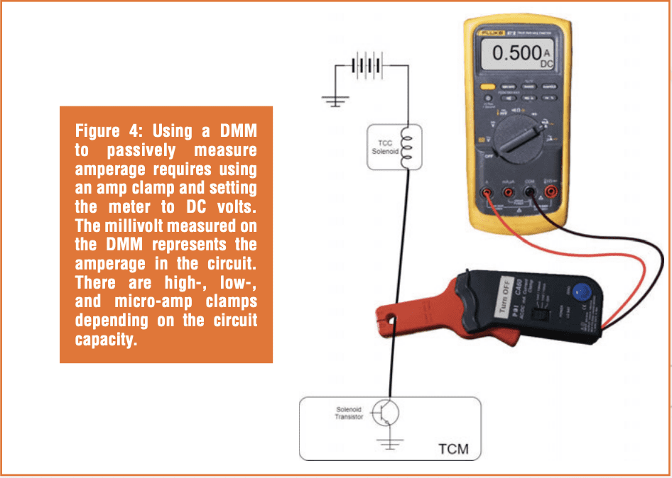
Placing the ammeter in series with the circuit requires either physically cutting a conductor or using jumper wires at a connection point. This is not an ideal situation, and it’s also why passive amperage testing is more common with micro-, low-, or high-amp current clamps (Figure 3). A passive current clamp is used in conjunction with a DMM or a scope. The clamp wraps around a wire and senses the magnetic field generated by the current. The tool then outputs a voltage to the DMM that corresponds to the circuit current (Figure 4).
![]()

Passive amp clamps expand the capabilities of amperage measurements through the following:
- No more blown meter fuses since there are no direct connections made.
- A wide range of amperages can be measured depending on the amp clamp size. High-current amp clamps work well for starting/ charging currents. Low-amp clamps work well with solenoid, pump, and fan motor currents. Even AF sensor currents can be measured with a micro-amp clamp, though micro-amp clamps are very expensive.

- Measurements can be made with minimal or no circuit modifications or manipulations. This is important when trying not to disturb a potentially bad connection that might “fix itself,” making further diagnostics difficult. A fuse loop (Figure 5) provides a convenient test point for amp clamps, allowing amperage measurements right at the power distribution box. Performing this measurement while using a scan tool to actuate a component on and off will validate computer control, circuit resistance (after Ohm’s law calculation), and circuit continuity through non-intrusive means.
- Passive amp clamps work great with scopes, showing a much more detailed picture of what’s happening in a circuit. The voltage produced by the amp clamp is easily traced on a scope, and it responds quickly to changes in amperage. Figure 6 shows the results of a low-amp current clamp when measuring a fuel pump circuit with a scope vs. with a DMM. Zooming in on the scope capture reveals a more detailed pattern that can be used to evaluate each segment of the fuel pump’s commutator. Using the scope’s measurement cursors shows the amperage settling at 13.75 amps, pretty close to what the DMM measures. In this example, the DMM displays 133 mV because the low-amp probe setting was set to 1 mV = 100 mA. Therefore, 133 mV is equal to 13300 mA (13.3 A). With an amp clamp and a DMM, a little decimal swapping is necessary, but the results are pretty accurate and quick.

SPECIFICATIONS AND CALCULATIONS
Published service diagnostics don’t often include amperage specifications. If you know the resistance of a component, such as a solenoid, you can calculate the current.  For example, if you know a shift solenoid should be 20 to 40 ohms, divide circuit voltage by the solenoid resistance to determine the expected circuit current. In this case, with a 12-volt source, a 20–40-ohm solenoid should draw between 0.6 and 0.3 amps respectively (voltage/resistance = current).
This still holds true for pulsewidth-modulated (PWM) circuits, but now you need to consider the duty cycle of the pulse to aid in the calculation, and just like for voltage measurements, remember that the DMM averages results.  For example, if an EVAP purge solenoid that has a spec of 10-30 ohms is connected to a circuit that operates at a 60% duty cycle (energized 60% of the time), you would expect the DMM to display 60% of the current, as shown in image seven. In this case, at the high end of the spec, a 30-ohm solenoid would pass 0.467 amps (467 mA) at 14 volts, but at a 60% duty cycle, the solenoid would only draw 0.280 amps (280 mA) (0.467 * 0.6 = 0.280). At the low end of the spec (10 ohms), the solenoid will pass 1.4 amps (1400 mA) at 14 volts, but with the same 60% duty cycle, current flow would be 0.840 amps (840 mA) (1.4 * 0.6 = 0.84). In the example shown in image seven, the current flow is slightly lower than expected, and the solenoid resistance is approximately 33 ohms.
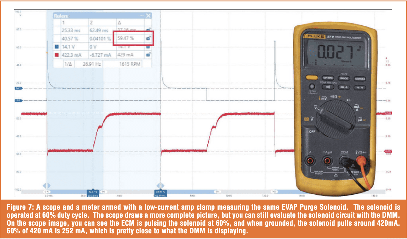 The averaging function of the DMM often leads to confusion because PWM circuits produce a pulsing current that is easily visible on a scope but is averaged out by the DMM. In fact, amperage measurement with a scope is much more common and beneficial than with a DMM, especially when evaluating electromagnetic coils. The shape of the amperage curve while the coil is energized can indicate shorted windings and excessive resistance, and, with some components, it can also indicate solenoid pintle movement. Figure 7 shows this pintle movement as a “hump” in the amperage trace.
COMMON MISTAKES WHEN USING AN AMMETER

Blown fuses – If you forget that the meter leads are left in the amperage setting and check voltage, you will blow the fuse, since voltage measurements are typically taken across or in parallel to the circuit. This allows high amperage to pass around the load and blow the fuse. Also, if you check a circuit that pulls more than the fuse is rated. Think back to Figure 6, which shows the current through a fuel pump. This pump drew over 13 amps, and if the fuse is rated for 10 amps, it could possibly blow.
If you’re checking a circuit and you see no current flow, it’s worth ensuring that the fuse isn’t blown before accepting the results at face value. 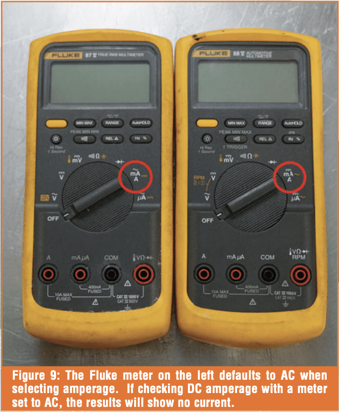 You can either disassemble the meter and check the fuse with the meter’s ohmmeter function, or, if you have another meter, you can check the fuse by measuring the resistance between the meter leads when placed in the amps/milliamps locations. Figure 8 shows a Bosch meter identifying a blown 400 mA fuse in a Fluke meter.
AC vs. DC – Meters designed for automotive use typically default to DC amperage measurements when initially selected, whereas meters intended for general or industrial use often default to AC amperage measurements. Figure 9 shows a common Fluke 87 and a Fluke 88 Automotive meter. The Fluke 88 (right) defaults to DC amperage, whereas the Fluke 87 (left) defaults to AC amperage. If this goes unnoticed, a technician might check a DC circuit, inadvertently leave the meter in AC amperage, see no measured current, and assume the circuit is at fault. On these Fluke meters, pressing the yellow button will switch between the AC and DC scales.
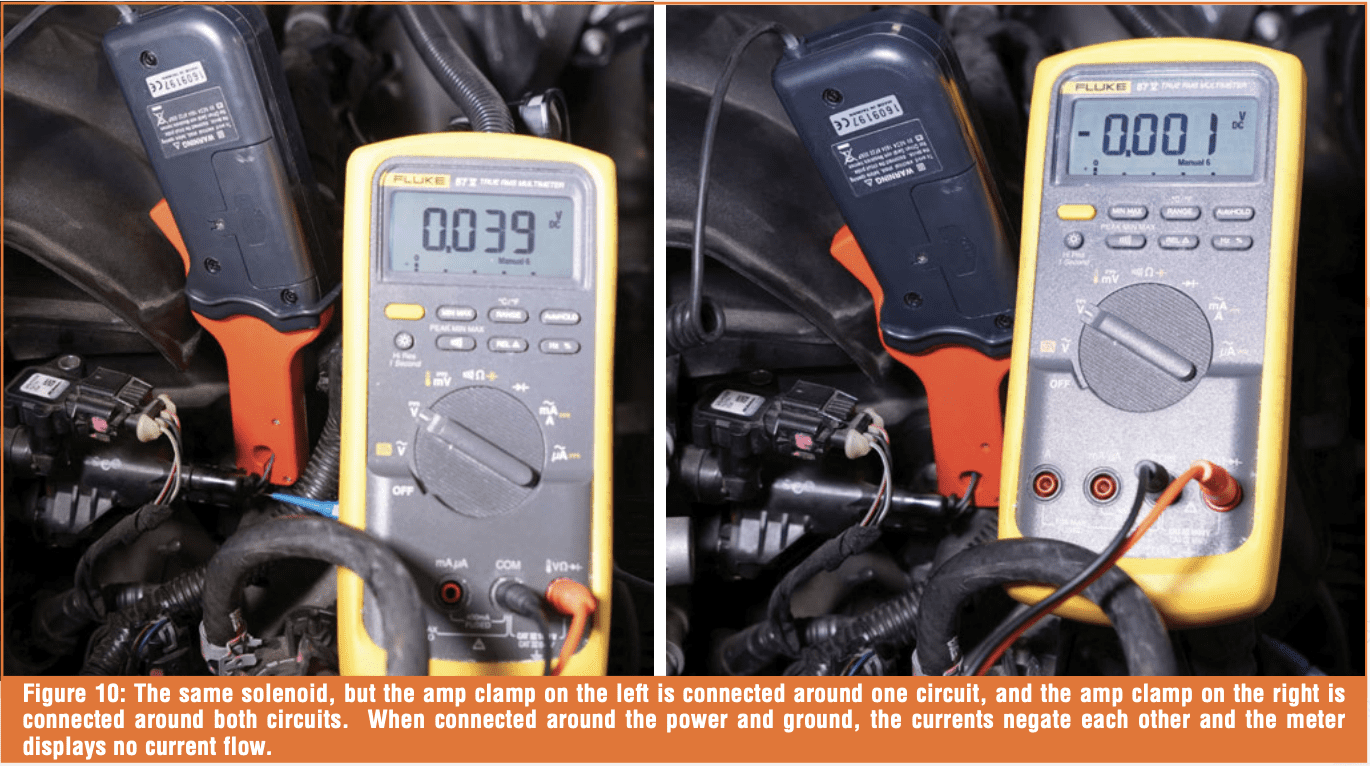 When using a passive amp clamp, set the meter to DC volts for measuring DC amperage. The amp clamp converts DC amperage to DC millivolts. When measuring AC amperage with an amp clamp, set the meter to AC volts. With passive amp clamps, a common mistake is clamping multiple wires at once, causing currents to cancel each other out. For example, as shown in Figure 10, if you placed an amp clamp around a power and ground circuit, the meter would read no current, since the two circuits are carrying the same current in opposite directions, canceling each other out. Similarly, if you check a power feed supplying multiple components, you’ll measure the amperage feeding them all. This might not be a problem, so long as it is intentional. For example, when checking a solenoid circuit through a fuse loop and that fuse is supplying multiple components, the technician can measure current flow with the solenoid commanded “off” and compare it to the current measured with the solenoid commanded “on”. The difference is the solenoid current, which can be used to calculate solenoid resistance if needed.
CONCLUSION
Although amperage diagnostics aren’t as common with a DMM as they are with a scope, there’s still value to this diagnostic test. Remember that with solenoids, actuators, and motors, it’s power (wattage) that allows the device to work. If you’re running into an electrical challenge, use amperage to further confirm circuit operation. But first, check that fuse in your meter, because there’s a 50/50 chance that it’s already blown!


