Transmissions have become quite complex in the past decade with advanced electronics, sophisticated solenoid and clutch application strategies, mechanical enhancements, and fluid chemistries. The 10L/10R series of transmissions has seen all of these advances, including hydraulic control via linear solenoids, sensors that read not only speed but also direction, and torque converter innovation with either tapered friction surfaces or pendulum dampening, just to name a few examples. The cooling system is no stranger to these advancements as well. Some 10L models use an advanced computer-controlled thermostat with an electric pump that directs cooled or heated fluid to where it’s needed, like on GM’s 2.7L turbocharged 4-cylinder L3B engine or the “baby” Duramax 3.0 LM2 (Figure 1).  These vehicles need thermal management for the cabin, engine, engine oil, transmission oil, turbo, and, in the case of the diesel, even the EGR and exhaust flow control valves. This makes for a pretty complicated system of pumps, valves, and sensors. How does this all tie into transmission operation?
GM and Ford shared many notes when developing their 10-speed transmissions, but there are still quite a few differences, and between the two brands, they experience different failures. For example, the CDF drum bushing issue is more prevalent with Ford than with GM. Some major differences between the units include GM significantly changing their valve body design; Ford sticking with the TCC that applies toward the transmission rather than the engine; shift strategies, with Ford using the “skip-shift” feature; and their transmission cooler operation, which some speculate may be the cause of the CDF drum/bushing failures.
![]()
Out of curiosity, I teamed up with a research-minded student, Kristy Rubino, and we decided to investigate the cooling system’s functionality in our school’s 2019 Ford F-150 to determine what “normal” looks like and how the transmission oil temperature would react to failures. She completed most of the legwork during these experiments through constructing test instruments, outfitting the vehicle with sensors, going on many test drives to collect data, running comparison vehicles on the chassis dyno, disassembling transmissions to inspect bypass circuits, then performing experiments on these bypass circuits to determine their normal function, collecting and analyzing data, plus I’m sure many more tasks. I greatly appreciate her contributions to this project. In Part One of this series, we will share the data collected during normal operation and some observations. In Part Two, we will share the effects of a couple of failures, and we will also compare the F-150’s cooling system to that of a 2022 Chevrolet Silverado.
COOLING SYSTEM LAYOUT
The 2019 Ford F-150 uses a coolant-to-oil heat exchanger mounted near the transmission. A simplified schematic of the system is shown in Figure 1. A Coolant Control Valve (CCV), mounted on the outlet side of the heat exchanger, up by the engine’s radiator, determines whether coolant is flowing or not through the heat exchanger. When the CCV is “off,” it’s mechanically open and coolant flows (the default state). When energized, the CCV blocks coolant flow. In our application, there is no bypass valve in the valve body, the cooler lines, or the cooler. Some Ford models equipped with an auxiliary oil-to-air cooler include a bypass for the additional cooler.
During start-up, all Ford 10R-equipped vehicles heat the transmission oil with engine coolant, since the coolant typically warms up faster than the transmission oil. At operating temperature, the transmission oil is cooled by coolant from the water pump, which is roughly at radiator outlet temperature. If the transmission oil exceeds the coolant temperature, heat will transfer into the coolant, effectively “cooling” the transmission oil, but only as low as the coolant temperature allows. By design, the transmission oil temperature should always be around this coolant temperature, or higher, since the coolantto- oil cooler ultimately determines the oil temperature.
 Since this is really a “thermal management” system that transfers heat to either increase or decrease transmission oil temperature, we refer to the “cooler” at times as a more appropriately named “heat exchanger.” Please take note that the terms “cooler” and “heat exchanger” refer to the same component.
RESEARCH QUESTION
Since it’s speculated that Ford’s naturally higher transmission oil temperature, when compared to GM, is the source of the CDF drum bushing “walk” failure, we set out to answer the following question: On the 2019 F-150, how efficiently does the Ford 10R cooling system exchange heat under normal operation, and what happens if the Coolant Control Valve fails “blocked”, or the heat exchanger’s oil passages becomes restricted?
![]()
EXPERIMENT
 After purchasing negative temperature coefficient (NTC) thermistors and basic electronics, Kristy designed and built an interface box (Figure 3) to connect the over-the-counter thermistors with the school’s 8-channel Pico scope. The interface box takes a 9-volt battery, drops it to 5 volts, and then delivers the power to six channels through a 1k ohm resistor. Externally, there is a connection for the thermistors, which change resistance with heat, and another connection for the scope, placed between the fixed 1k ohm resistor and the thermistor, as the schematic shows. This allowed us to measure a voltage between the fixed resistor in the box and the thermistor, and that voltage corresponded to a specific temperature. Then, by programming the scope with a voltage-to-temperature table, we were able to monitor temperature at six locations. By taping thermistors to the points labeled in figure two, Kristy collected temperature data under normal and failed conditions. She also monitored the ground-side voltage of the CCV solenoid to determine the state of the flow-control solenoid.
Looking at a scope image with multiple traces can be confusing, but the longer you stare at it, the more it makes sense. Figure 4 shows a normal drive, starting with a cold engine and then driving until the engine coolant and transmission oil have warmed up and temperatures have stabilized. The ambient air temperature was 72 degrees F, and the driving style was normal acceleration/deceleration, on a mixture of flat and hilly roads, combining both highway speeds and stop-and-go. The scope pattern is zoomed in to show about 20 minutes of driving. Scope channels A through F are connected to thermistors and directly measure the temperature of the metal, plastic, or rubber lines at the points indicated in figure two. Channel H (burgundy) is connected to the CCV’s ground circuit to determine if the PCM ever energized the solenoid to close the valve.
 A few observations worth noting regarding the normal drive and typical transmission operation, as shown in figures 4 and 5:
- During warm-up, as expected, coolant OUT temp dropped, and trans oil temp OUT increased, showing the effectiveness of the cooler as a heat exchanger transferring coolant heat into the transmission oil. On average, there was about a 13-degree F drop in coolant inlet/outlet temperatures during warm-up.
- Transmission oil temp had an even greater temperature change, averaging an increase of about 36 degrees F during warm-up when comparing inlet to outlet.
- During normal driving, with all temperatures stabilized, the transmission oil temperature was consistently about 5 degrees higher than the coolant inlet temperature.

- The thermal management system acted more as a “warmer” than as a cooler for the first 15 minutes of driving.
- On our F-150, when the TCC was applied, the TCC slip stayed around 0 RPM. Since the converter slip is responsible for most of the heat in a transmission, keeping the converter locked slows the temperature rise.
- During all of our tests, some of which included starting from below-freezing temperatures to high-temp brake torquing, which forced transmission oil temps to climb over 250 degrees, the CCV was never energized. It always remained electrically OFF, allowing coolant flow.

Figures 6 and 7 show a 1700 RPM brake torque, indicating how quickly the trans oil temp climbs when the transmission is under load, and the TCC is not applied. These measurements show how effectively the coolant-to-oil exchanger can absorb this heat. A few observations worth noting:
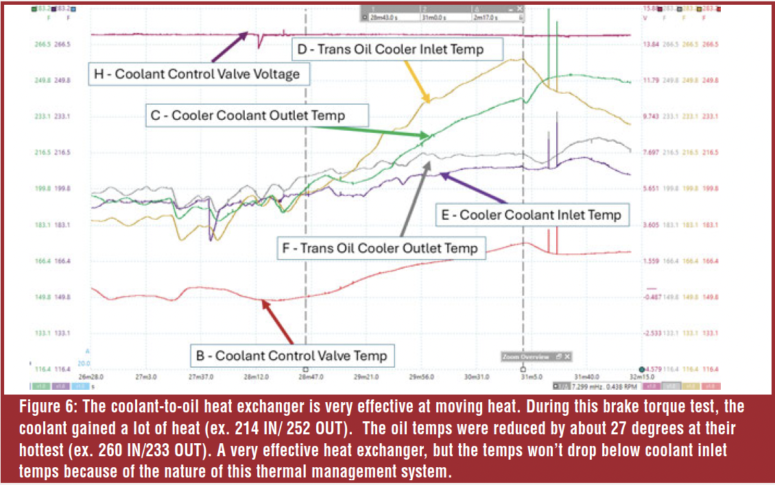 The scan tool transmission temperature PID matched closely to channel “F,” Trans Oil Cooler Outlet temperature. We backed off when the Trans Oil Cooler Inlet Temp reached close to 260 degrees, but we’re sure it would have continued to climb if allowed.
The oil temperature climbed steeply, and the heat exchanger did a great job of transferring heat, but because there’s no oil-to-air cooler, the transmission oil temperature couldn’t drop below the coolant temperature.
 After releasing the throttle to allow the temperatures to drop, the heat exchanger had difficulty lowering the transmission oil temperature, as can be seen by the trans oil IN and OUT traces moving toward each other. This might be due to the reduced coolant flow as engine speed dropped. As a result, even though the transmission oil IN temperature dropped, the OUT temperature continued to climb, because the coolant IN temperature also climbed.
CONCLUSION
During these tests, we didn’t see the markedly high oil temperatures often reported for the Ford 10R transmission, but we weren’t pulling a trailer or operating in very high ambient temperatures. This experiment was still a good physics lesson that enforced the laws of thermal dynamics and gave us a clear look at heat transfer in the F-150’s thermal management system.  Some limitations of this cooling system include the inability to drop below coolant temperature under high-load conditions and the lack of an air-to-oil cooler to further reduce oil temperature if needed. In the next article, we’ll show how this system reacts to a CCV stuck closed failure and a restricted cooler failure. Also, we’ll compare this thermal management system to the more conventional transmission cooler system found on the 2022 Chevrolet Silverado; two transmissions that are basically the same, but with different control strategies and vastly different thermal management systems.


