
Road Test, because you can’t confirm your repair without it. A road test is your first, and sometimes only, chance to identify a problem. It may be performed before touching a single wrench. Too many technicians still perform the “P-R-D road test” (Park > Reverse > Drive), drive around the block, and call it good.
A real diagnostic road test is deliberate, structured, and designed to separate hydraulic issues, mechanical issues, electronic/command issues, and outside contributing factors. Follow this step-by-step guide to road test like a professional.
STEP 1: SAFETY FIRST
Before the vehicle moves an inch, confirm that it is safe to operate.
Perform a pre-drive safety check. No loose body panels or undercar components (e.g., bumper covers, exhaust shields, trim), as well as brakes and suspension are in good working order. If the brake pedal drops to the floor when you press it or a wheel assembly is loose, do not operate the vehicle in traffic. Nothing should obstruct visibility through the windshield or windows. Nothing may interfere with the pedal assembly, steering wheel, or driver operation.
Verify PARK Function – Most Critical Safety Check
Ensure the transmission holds the vehicle on an incline. A failing park mechanism, poorly adjusted shifter cable, or faulty park-by-wire system can allow unintended vehicle movement. Always verify this before exiting the driver’s seat.

STEP 2: CHECK FOR ENGAGEMENT QUALITY
How a transmission enters gear reveals critical information about hydraulic health and command strategy. Watch for reverse and forward engagement delay, slow or soft engagements, harsh or hard engagements, and double-bump into Drive or Reverse. These are not specific diagnostic steps, but rather a direction for your diagnostic process.
Slow engagement may be caused by low line pressure (commanded or actual), failing pump, pressure control valve issues, aerated or low fluid, lack of line rise command, misadjusted shift cable, torque converter drain-back (internal fluid draining into the pan, requiring a refill time before movement).
Hard engagement may be caused by excessive line pressure from a stuck EPC/ PCS solenoid, PCM commanding maximum line pressure due to failsafe/limp mode, misadjusted range sensor, broken or collapsed engine or transmission mounts, incorrect or contaminated fluid affecting clutch application, poor grounds or voltage drop. Most transmission control systems default to maximum line pressure when electronic control is lost.
Compare engagement feel to OEM “garage shift time” specifications. Most manufacturers publish acceptable engagement windows. Anything outside those ranges is a diagnostic clue.
STEP 3: DRIVE WITH INTENT, NOT HABIT
A proper road test exercises every mechanical range and command strategy. Not just Drive.
Manually select all available ranges: Manual 1 (Low), Manual 2, Manual 3 (if equipped), Drive, Overdrive / 5th / 6th / 8th / 10th / etc., Sport, Snow, Tow/Haul, and other drive modes. Consult OEM service information for your specific platform. Each range and mode has unique strategies.
What you’re evaluating are the following:
- Does the transmission hold the commanded gear under load?
- Does the vehicle provide engine braking in lower gears?
A free-rolling condition in low gear may indicate a failed sprag or roller clutch.
Example Diagnostic Clue: If Manual 2 holds correctly, but Drive 2 slips, the clutch element used in Manual 2 is likely not failed. This allows you to eliminate certain components using the clutch application chart.
Bring Your Scan Tool
A scan tool does not tell you which component failed. It tells you which system has a fault and helps you in the diagnosis of those components.
During the road test, it allows you to monitor or control solenoids, TCC apply/release, line pressure commands, adaptive resets / clutch learn, and shift timing. Bi-directional control can dramatically accelerate diagnosis, especially for intermittent concerns.
STEP 4: KNOW YOUR SHIFT POINTS
Shift timing is engineered, not random. If you don’t know what should happen, you can’t diagnose what shouldn’t.
You should know expected shift points at light, moderate, and heavy throttle; when TCC lockup should apply and release; commanded speeds for 3–4, 4–5, etc.; and how failsafe behaves; fixed gear, maximum line pressure, no-move condition, limited speed.
Where to Find Shift Specifications
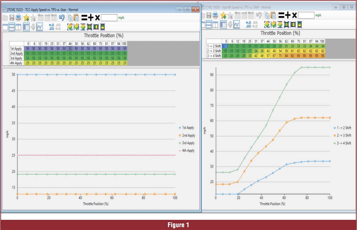
Data services like Alldata, Mitchell1, Identifix, and OEM service websites provide needed specifications. Figure 1 is a typical HP Tuners shift schedule for a 6L80 (1st–4th gears). This shows what the PCM expects to happen. Any large deviation from commanded behavior indicates a fault, meaning something inside the transmission is not responding as instructed.
STEP 5: FEEL FOR SHUDDER, FLARE, DELAY, OR HARSH EVENTS
Shudder
Often misdiagnosed as TCC failure, but can also be caused by AFM/DOD transitions, driveline vibration, ignition misfire, poor-quality or contaminated fuel, or direct injection malfunctions. A skilled road test distinguishes engine issues from torque converter shudder.
Flare
A rise in RPM between shifts without corresponding acceleration.
Common causes are low line pressure, defective shift solenoid, contaminated or burnt fluid, internal clutch wear, incorrect MAF/MAP data affecting shift timing, internal leaks, or pressure loss. Data logging is essential here.
Delay
A later-than-expected shift; not a slip nor a bind.
Often caused by a stuck shift valve, PCM command delay, driver-selected modes (tow/haul, tap shift, etc.), incorrect tire size, or axle ratio (VSS mismatch).
Harsh Shifts
Harsh “bang” shifts typically indicate poor clutch timing (oncoming and off-going clutches applied simultaneously), line pressure higher than commanded (EPC/ PCS issue), broken or collapsed mounts, high line pressure from failsafe strategy, failed accumulator or dampener circuit.
Pattern Recognition Matters
Every shift is harsh usually indicates an overall line pressure issue. One shift harsh usually indicates clutch-to-clutch timing issue.
STEP 6: VALIDATE COMMANDS VS. RESULTS
Your senses are good. Data makes them better. Use a scan tool to compare commanded gear, commanded shift pressure, actual line pressure, desired versus actual TCC slip, output shaft speed, input shaft speed (if equipped).
If the PCM commands a shift but the ratio does not change, an internal hydraulic or mechanical failure is likely. If the PCM does not command a shift, an input, sensor, or electrical issue is likely.
HP Tuners VCM Scanner/Editor is an excellent tool for visualizing these relationships.
STEP 7: DON’T FORGET FAILSAFE BEHAVIOR
Many transmissions enter failsafe due to external issues, not internal damage.
Common failsafe modes include one forward gear plus reverse, high line pressure, no-move / Park-only, limited throttle or RPM, speed-restricted operation. OEM manuals list the exact triggers, including DTCs and the resulting failure mode. Understanding failsafe behavior prevents unnecessary transmission replacement.
Replicate the Customer’s Conditions
When performing your road test, it is critical to replicate the conditions under which the customer reported the issue. This may require specific operating temperatures or a certain distance driven. A good service writer can save valuable diagnostic time by documenting these details accurately.
It is also beneficial to test the vehicle under multiple driving styles. Accelerate through all shifts: light, moderate, and heavy throttle. Beware of speed limits and the safety of other drivers. Use common sense here.
Adaptive Behavior Matters
Modern transmissions learn and adapt to driving behavior.
If a slip is noticed during a 4–5 shift at moderate throttle, document throttle input, vehicle speed, and load. Then attempt to reproduce it multiple times. If the PCM had never previously encountered that slip, it may adapt and correct it. That does not necessarily mean there is a failure, but rather, it shows the system is operating as designed.
THE BOTTOM LINE
A correct road test is not optional. It is structured, intentional, and rooted in OEM data. It helps determine whether a problem is hydraulic, mechanical, electrical, sensor-related, driver-induced, or modification-induced.
A quick P-R-D test misses over 80% of meaningful diagnostic clues. When you know what “good” looks and feels like, you will recognize “bad” instantly.


