
This article is part two of a series that focuses on the limitations and considerations of common measurements performed with one of the most commonly used diagnostic tools, the Digital Multimeter (DMM). In the November 2025 issue, I addressed some of the limitations and misuses when using the voltmeter setting. This article focuses on the ohmmeter setting, which one would think is very intuitive and less prone to error. For the most part, this statement is true, but some ˆ need to be considered when performing the basic resistance test.
OHMMETER FUNCTION AND USAGE
The uses for the ohmmeter are obvious – you can measure circuit and component resistance and check for circuit continuity. Service manuals often publish the resistance of solenoids, actuators, and some sensors, so the tech has a specification to reference. The process of measuring resistance involves removing power from the circuit and isolating the component or circuit to be tested (Figure 1).


METER OPERATION
The ohmmeter calculates the resistance of a circuit or component by placing a small amount of current, usually 1 mA, while measuring the voltage drop across the meter leads. The resistance is then calculated using Ohm’s law. You may recall Figure 2 from last month’s article, which shows the high internal resistance of a selection of voltmeters set on the DC scale. Maybe you also noticed that most of the voltmeters were reading about 2.7 volts. The voltmeters at the top of the image were measuring the voltage that the ohmmeters at the bottom of the image placed on the circuit to calculate resistance. In this example, the ohmmeters were pushing only 0.00000027 amp across that 10M ohms of voltmeter resistance, and that forced the 2.7 volt drop across the voltmeter.
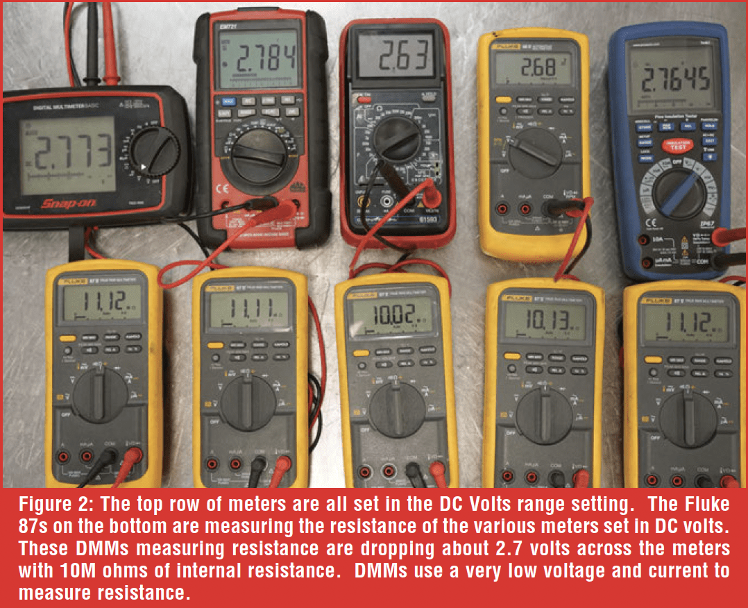 Figure 3 shows another experimental measurement related to a more common diagnostic task. The ohmmeter measures a variable reluctance speed sensor with 515 ohms of resistance. You can see the amperage (1 mA) provided by the ohmmeter and the voltage drop (0.515V), which would be measured by the ohmmeter. With these values, you can see how the meter can use Ohm’s law to calculate the sensor’s resistance. The point of this demonstration is to prove that an ohmmeter operates by placing a very small amount of current through a circuit and then measures the voltage drop to calculate the resistance.
![]()
LIMITATIONS
How intact does a circuit need to be to pass a resistance test? If I had a circuit that was “hanging on by a thread,” literally, would it pass?  Figure 4 shows a resistance measurement of a single strand of wire. This wire would pass a resistance test according to ohmmeter-based diagnostics (measured 0.3 Ohms, which is about the same as placing the leads together), but it won’t handle operating a component that requires a “decent” amount of current flow.
Figure 5 shows the results when I increased the current through the circuit until there was a significant voltage drop across that single strand of wire. The circuit reached about 1.5 amps before it heated up dramatically and started dropping voltage.
 MANUFACTURER’S PREFERENCE

Even though the ohmmeter has a serious limitation of not adequately loading a circuit while testing, some manufacturers still prefer this diagnostic method, likely due to its reliability and ease of application. After comparing the published DTC-based diagnostics between GM, Ford, and Stellantis on a TCC solenoid, you’ll find that each manufacturer varies their diagnostic process and has a different level of faith in the technician.
- Ford, using a 2023 F-150 as a reference, still relies heavily on resistance testing, and it doesn’t necessarily explain what each test is performing. Review a wiring schematic to determine the purpose of each measurement. One thing you’ll note is that if they’re expecting continuity, you’ll see an expected measurement of 3 ohms or less. If they are expecting an isolated circuit, you’ll see an expected measurement of 10,000 ohms or more.
- GM, using a 2023 Silverado as a reference, uses a mix of scan data, test lamp, resistance, and voltage to evaluate the TCC circuit. Using a test lamp ensures that the circuit can carry current, but make sure to use a test lamp that draws significant current. Many test lights are simply LEDs, which hardly require any current to light. GM uses the test lamp to evaluate the circuit, and once a problem is discovered, the diagnostics lead the technician to use an ohmmeter to find the fault.
- Stellantis, using a 2023 Ram as a reference, uses a mix of diagnostics based on scan data results. Still, they also rely heavily on resistance testing to evaluate a circuit and determine the cause of a DTC.
 One thing that is common among most examples is that the diagnostics immediately lead the technician to disconnect connectors, which is a requirement of resistance testing, since you need to isolate the circuit. Keep in mind that if the DTC or symptom is intermittent, disturbing connectors and wiring might temporarily cover up the intermittent. It might be best to go “off script” and perform diagnostics that are the least intrusive, such as scan tool-based diagnostics, back-probing, and measuring voltage drop.
LOW RESISTANCE/HIGH CURRENT MEASUREMENTS
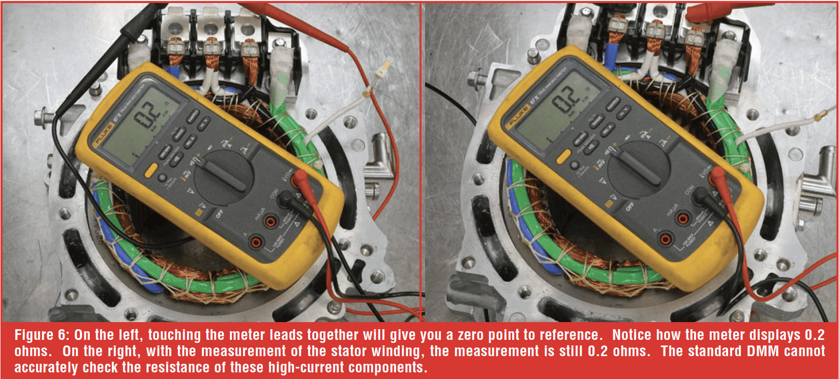
The primary side of an ignition coil and the windings of an electric motor naturally have very thick wires to allow high current flow. These items, when measured by a standard DMM, will show very low or possibly no resistance. Figure 6 shows me touching the meter leads together to indicate a zero point, and then I performed the resistance test on the stator windings of an EV motor. Notice how the resistance values are the same. This is because the thick winding easily passes the current supplied from the ohmmeter, and therefore, the ohmmeter measured very little voltage drop. This severely limits the diagnostic ability of a standard DMM when checking these high-current circuits. They can effectively check for open circuits, excessive resistance, and direct short-to-ground failures. Still, they are not accurate enough to check for winding-to-winding shorts, which is a more common issue with high-current coils and motors. In these situations, a milliohm meter is necessary.
The milliohm meter places a higher current (typically one amp) through the circuit and measures the voltage drop across the load. The standard milliohm meter has two leads on each probe: one to place the current and the other to measure the voltage, as shown in Figure 7. The meter then uses Ohm’s law, along with some temperature adjustments, to calculate the resistance, which in this case comes out to 14.6 milliohms (.0146 ohms).
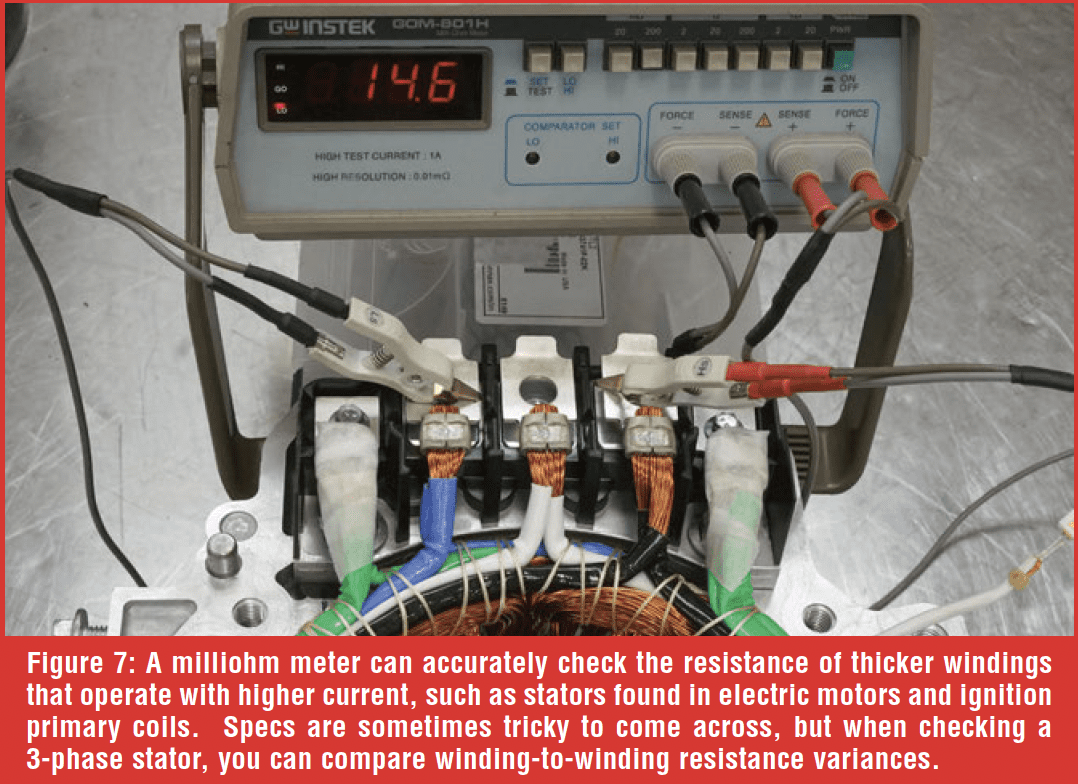 It might be challenging to find specifications for high-current windings, so comparing the results to a known good, or, in the case of the 3-phase electric motor, you can compare the phases to each other. Referring back to Figure 7, if the technician completed three measurements between the three windings and compared the results, the resistance of each of the three phases should be within 5% of each other. If the reading varies more than 5%, you can suspect a winding-to-winding short. If you’re working on Hybrid and EV vehicles, consider adding a milliohm meter to your electrical diagnostic kit, if you haven’t already. You can actually make a milliohm meter using two DMMs and a 12-ohm resistor, but that’s a topic for another article.
HIGH-VOLTAGE ISOLATION OHMMETERS
Most hybrid and EV motors operate at a high voltage, upwards of 900+ volts! The high-voltage system operates independently of the low-voltage system. The circuits don’t share grounds or current paths. The high-voltage controllers are constantly monitoring to see if high voltage is “leaking” into the low-voltage side. If it does, a module will set a “loss of isolation” DTC. To diagnose these faults, the technician needs to use a Megohm meter.
The megohm meter works with the same principle as the standard DMM, but instead of placing a low voltage on the circuit, the megohm meter injects a high voltage, typically selectable between various high voltage settings, such as 250, 500, 750, and 1000 volts. The technician is supposed to select a voltage one step higher than the operating voltage. For example, if the vehicle uses a 400-volt system, then the megohm meter is set to 500 volts.
When using the megohm function, the desired result is a very high resistance, such as one giga-ohm or greater. There’s actually a specification of 500 ohms per volt established by the Federal Motor Vehicle Safety Standard (FMVSS) 305, which would require a 400-volt system to have a minimum of 200k ohms of isolation. However, manufacturers typically set their isolation fault tolerance at a much higher resistance. When the megohm meter exposes a fault through pulsing high voltage, it indicates that current is leaking past the circuit insulation and finding its way to ground. 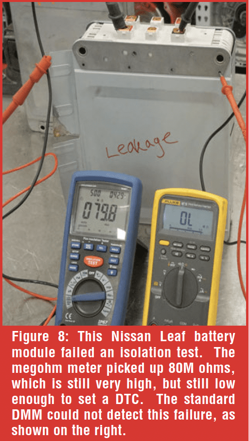 Refer to Figure 8, where a Nissan Leaf battery is failing the megohm test due to a leaking battery. It still has high isolation resistance at 80M ohms, but this battery module set a DTC. Just for reference, I also included a standard DMM to show its inability to detect this current leakage. While the megohm meter measured 80M ohms, the Fluke 87 couldn’t force the short and displayed ‘OL’. With a good battery module, both meters would display OL as shown in Figure 9.
While checking electric motors, the megohm meter isn’t checking for shorts between the windings; that’s the role of the milliohm meter. The meter is checking for shorts between the windings and ground. If you had a complete short, you wouldn’t need a megohm meter, as the standard DMM would detect this fine. You need the megohm meter to see if the insulation is breaking down or a component is failing under high voltage. Standard megohm meters include the Megger MIT 230 and the Fluke 1507, but the Pico TA 467 is a DMM that incorporates a megohm meter. 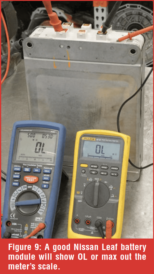 A little side note on the Pico TA 467: be sure to place the leads in the appropriate spot when performing a megohm (isolation) test. If you don’t, you will still be able to complete the test, but the result will always indicate passing, because you’re not actually testing anything. With image nine, the two probes are placed in the spots labeled “isolation +” and “isolation –,” which are in small print and can be easily missed.
COMMON MISTAKES WHEN USING AN OHMMETER
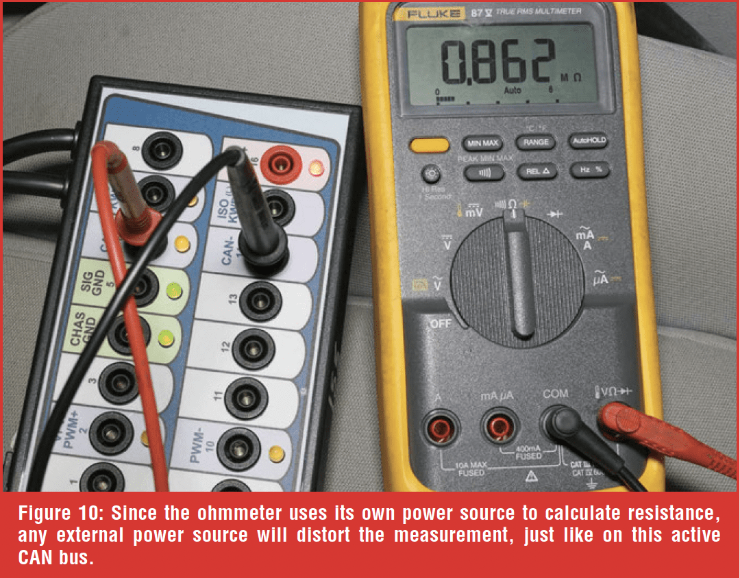
- Measuring a powered circuit – Ensure that there’s no power on the circuit. I’ve witnessed students checking for the normal 60 ohms of resistance across the CAN “+” and CAN “-”with inconsistent results (Figure 10). They assume there’s an issue with the CAN, but, in fact, they didn’t ensure the network was depowered, and the normal CAN voltages caused erratic DMM measurements. The voltage on the circuit interferes with the voltage the meter uses for the calculation. Something as simple as leaving the door open can cause the CAN to stay awake. Keep that in mind when diagnosing communication faults.
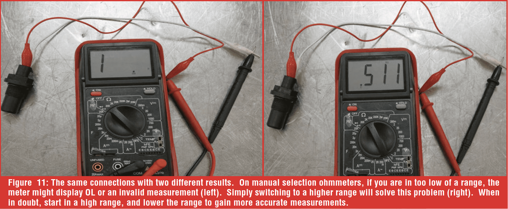
- Improper range – Most meters have auto-ranging features, but some meters still require range selection. If you are checking a higher resistance component but have the range set too low, the meter will likely display ‘OL’ (out of limits) or give an invalid value, as shown in Figure 11, which the technician might interpret as an open circuit or faulty part. It’s good to start higher than the spec and lower the range as needed to get a more accurate measurement.
- Non-isolated circuit – when checking a connected circuit, especially on a circuit board, the ohmmeter might measure a parallel path and provide unexpected results, or a component might have an open circuit. Yet, the meter can back-feed through other components and still show continuity. It’s wise to isolate the component tested, even if it means doing the extra work of desoldering the part on a circuit board.
- Low resistance typically indicates a good circuit – Knowledge of the circuit is crucial when performing resistance-based diagnostics. The meter will likely give passing results on a circuit that has a connection, but the connection must be adequate to handle the current required by the component. Any circuit that has an actuator, solenoid, motor, pump, or anything that carries a decent amount of current could ohm-test with passing results but fail under operation. This is why performing a voltage drop test instead of resistance is always a better method for circuits that require a decent amount of current. In low-current circuits, like sensors and networks, the ohmmeter does a great job.
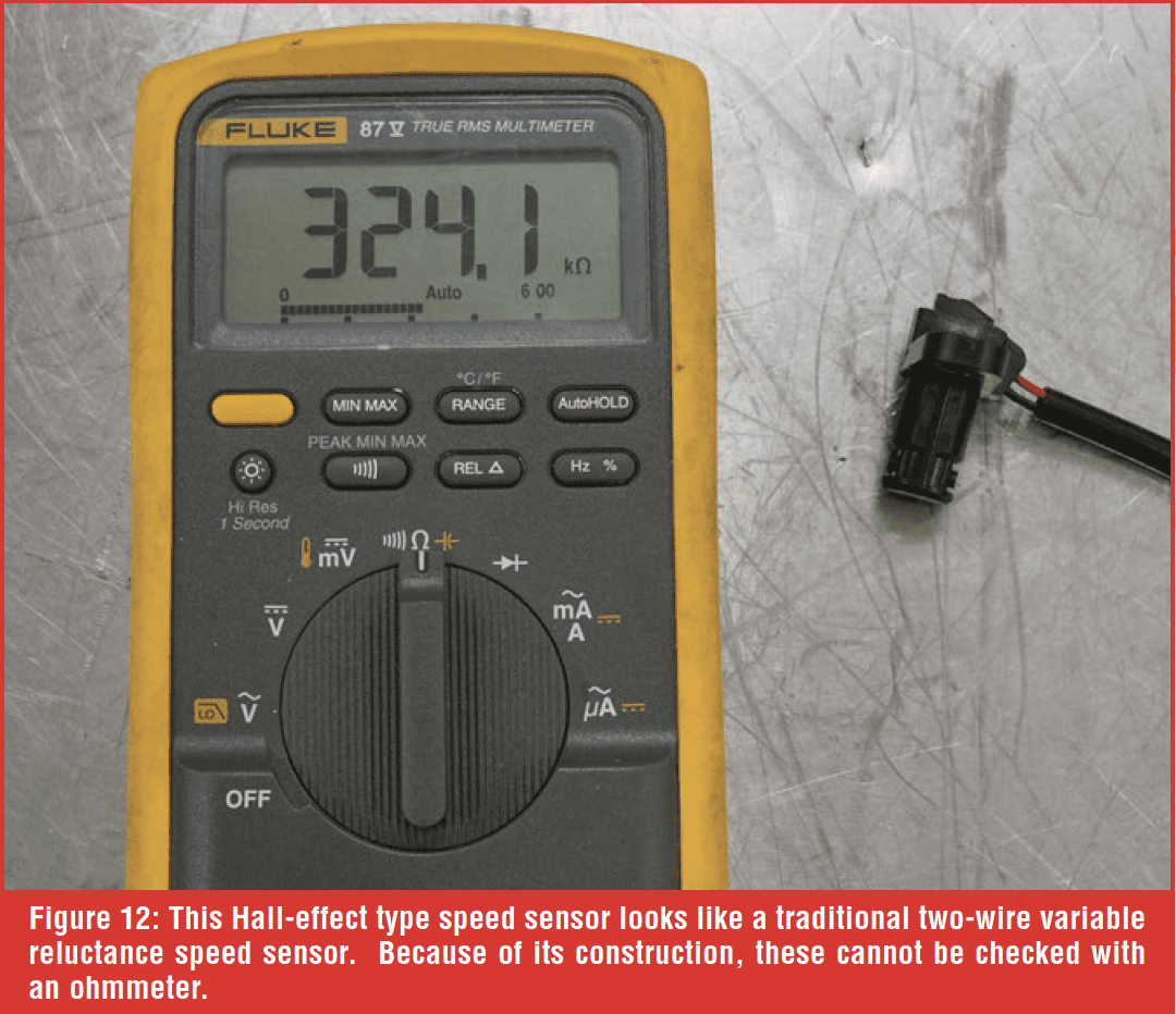
- Checking transistorized or solid-state components – many components have ditched the traditional coil or resistive-based design for a computerized “smart” construction. Speed sensors and relays, for example, are often their own integrated circuit. Checking these circuits with an ohmmeter will result in very high resistance readings, which will not lead to an effective diagnosis. With these components, a scan tool and a scope will be your best option to confirm proper operation. Figure 12 shows a two-wire, hall-effect type speed sensor that could easily be confused with the common two-wire variable reluctance type sensor. As you can see, this perfectly normal speed sensor measures at 324K ohms, which would be way out of spec for a VR-type sensor.
CONCLUSION
An ohmmeter is an essential diagnostic tool, but it’s important that the tech has a solid understanding of the measured circuits and components, and also understands the ohmmeter’s limitations. Not all ohmmeters are the same. Standard DMMs do a good job with common circuits and components. A milliohm meter is necessary to check high-current/thick-winding circuits accurately. A megohm meter is necessary to stress the high-voltage circuits and components and ensure isolation from the low-voltage system and the chassis. The next article will explore the ammeter function of the DMM – let’s hope the fuse isn’t blown!


