
In recent past issues, I’ve covered the basic uses and misuses of the Digital Multimeter (DMM). This series will introduce you to the value of the digital storage oscilloscope (DSO) and its common uses and misuses. I’ve written on scope usage in the past (search “scopes” at www.gearsmagazine.com), and that content is still very relevant. The purpose of this series is to take the technician who feels confident in their DMM skills and graduate them to the DSO. I truly believe that a technician with a solid understanding of basic electrical principles, confidence in their DMM skills, and an inexpensive DSO can become proficient in scope-based diagnostics.
INVESTMENT
Scopes can be expensive. If you are new to scopes and do not currently own one, I suggest buying a relatively inexpensive starter scope. There are plenty of internet specials and enticing deals, but keep in mind that the scope’s software will make or break the learning curve. Try to find a scope with frequent software updates that improve the user experience and has plenty of features. For example, the Hantek 6022BE is a pretty capable scope, and it’s really cheap ($65), but the software available from Hantek hasn’t been updated since April 2013.  Whereas the Pico 2204a, shown in Figure 1, is a $200 scope equipped with a basic lead set, and its software is frequently updated and fundamentally the same as the automotive software. This is a great option for learning scope usage without making a large $ 2000+ investment.
Quality software will allow the tech to store multiple scope screens, filter signals, perform measurements, and create custom ranges if needed. Even without a Pico scope, you can download, install, and experiment with the Pico software for free at picotech.com (for generic scopes) and www.picoauto.com (for automotive scopes). If you obtain a 2204a, you must use the generic software from www.picotech.com. Only automotive-specific scopes work with the automotive software. The main difference between generic and automotive software is that automotive software includes waveform libraries and recommended settings for common automotive components. Of course, there’s nothing stopping you from downloading the automotive software and mimicking the settings between the two versions.

VALUE OF A SCOPE
The DMM can effectively diagnose most electrical issues, but there are times when you are left wondering what the electrical signal actually looks like. If you read the DMM series, I pointed out that the DMM averages readings, so when measuring PWM circuits or fast switching sensor circuits, the meter displays an average value. Using a scope in these situations, the technician will see the actual pattern. Plus, a DMM might miss or poorly represent glitches, signal dropouts, and noise. The scope, along with its high sample rate, will show exactly how the circuit is performing. A perfect example of this is CAN bus monitoring. It’s possible to diagnose a network issue with a DMM, but a scope will do a much better job showing faults, abnormal, and normal communication.
Plus, anything that can be converted into a voltage can be displayed on a scope. Common examples include amperage, temperature, pressure, light, and vibration. But before jumping into advanced measurements, let’s get comfortable with simple tasks with an inexpensive scope.
SCOPE BASICS
Simply stated, a DSO displays voltage over time. The vertical scale displays voltage, and the horizontal scale displays time (Figure 2). These settings are adjustable to accommodate the measurement being performed. 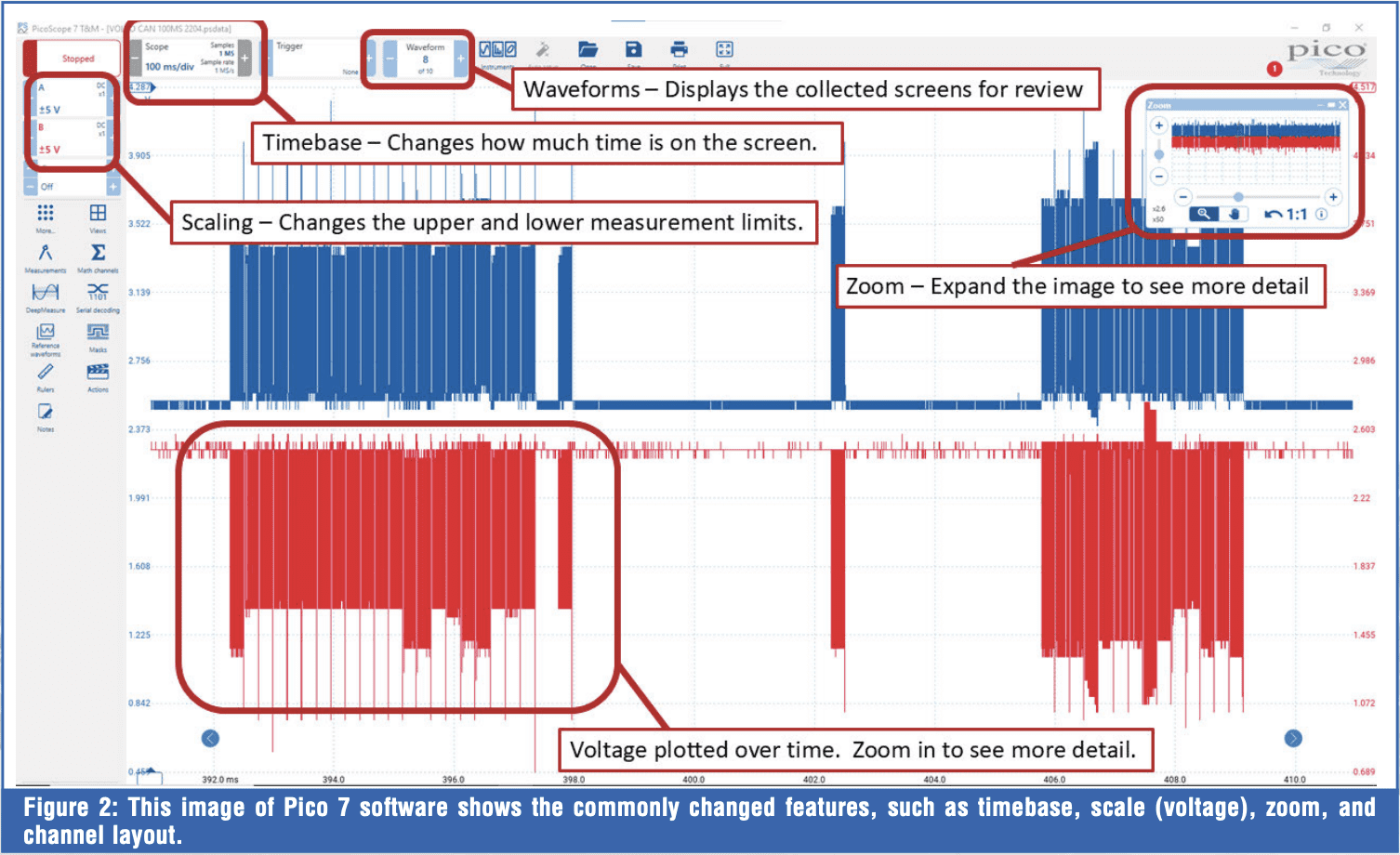 This is where many techs appreciate the automotive-specific software, because they can select a sensor or actuator from a menu, and the scope will automatically adjust to the predefined setting for that type of measurement. If you are using the inexpensive, non-automotive scope, you will need to set up the scales manually. But this is not a problem! Use your knowledge of component and circuit operation to set up the scope, because in many instances, it really comes down to personal preference.
BASIC SCOPE SETUP
When using an inexpensive scope to hone your skills, I suggest starting with a lot of time on the screen. Often, the scope’s software initially starts at way too fast of a timebase by default. For example, when Pico 7 Testing and Measurement (T&M) is first opened, the timebase is set to 1ms/div. This means that each of the ten vertical marks is only 1 millisecond apart, and the total screen time is only 10 milliseconds, which is only 1/100th of a second. At this timebase, a nonswitching pattern may seem to jump around erratically. To obtain a better picture, add time to the capture. Personally, I like to start with 100ms/div on the screen. In this setting, the scope is set to display 1 second per screen. Here’s a little tip if you are using the 2204a: click the scope’s timebase box, then select “sampling,” then adjust “progressive mode” to as low as it will go (likely 100ms), then increase the “sample rate” to 2MS (Figure 3). This will max the scope‘s sampling capabilities. In this setting, so long as the scope’s time base is set to 100ms or greater, the scope will capture 1 million samples per second, as identified in the timebase box. This method will allow the scope’s hardware to collect more samples to display. Otherwise, if this scope is set below 100ms/div, the sample rate will drop off considerably (Figure 4). This is unique to the inexpensive Pico 2204a, but after considering this limitation, you can better utilize its capabilities. When capturing a fast-switching signal, if the pattern is too condensed, collect a screen or two of data, then pause the scope and zoom in (Figure 5). You’ll find that the signal is there, clean and accurate, and you can evaluate it for issues with confidence.
 Remember that the scope is simply a tool. Before checking any signal, you should have an idea of what that signal should look like. Study a wiring diagram, connect the leads, and grab a sample to verify your assumptions. Perform some measurements to determine whether the voltages are within their proper range. Check the relationship among multiple channels (signals) to determine whether they are synchronized. This might require you to review service information or search for known-good waveforms for reference. When learning to use the scope, spend some time taking measurements on known-good vehicles to train your brain on what to expect.
SCOPE MISUSES
Max voltage
Scopes come in different sizes and capabilities. The expensive automotive 4425 has a max input voltage of 100 volts. 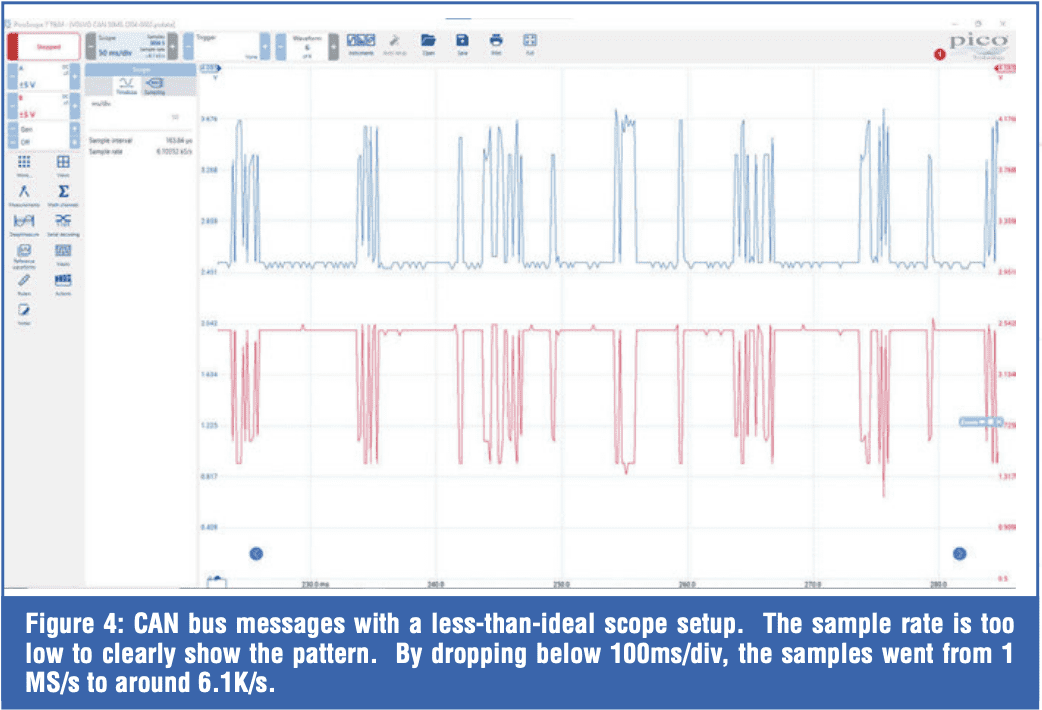 This is great, because accidentally measuring an injector that kicks back with an inductive spike of 70 volts won’t damage the scope. Earlier automotive Pico’s had a lower input voltage rating of 50 V or 100 V. The 2204a has an input rating of only 20 V, which may seem impractical for automotive use, but the leads include a switchable attenuator that can be set to 1x or 10x (Figure 6). When set to 10x, the leads drop the input voltage 10 times, so the scope sees 1/10th of the measured voltage. This means a 70-volt injector spike will be reduced to 7 volts at the scope. To correct the scaling, you can change the “probe” setting for the scope channel to 10x (Figure 7). Now the values displayed will accurately reflect the measurement. Often, 2204a users purchase better leads and separate attenuators for checking higher voltage.
If using the supplied leads, keep the switch setting in mind. I’ve had students accidentally switch the leads to 10x and wonder why they couldn’t get a decent pattern. The pattern was there; it was just 10x smaller than expected due to the inadvertent switch setting.
A good practice is to use an attenuator when measuring output devices (such as relays, actuators, solenoids, or electromagnetic components) to protect the scope. 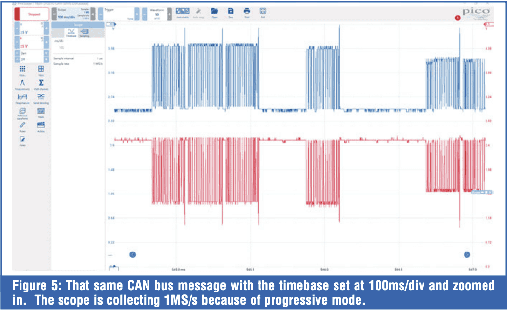 If the pattern doesn’t show spikes or high voltage, you can remove the attenuator if desired. Relays, solenoids, and injectors can spike to 70 volts. The real scope killer is the primary ignition, which will spike to around 400 volts.
DMM VS. SCOPE
Many DSOs use shared grounds across the different channels. Because of this, I don’t recommend measuring across sensors or components unless you know your scope is capable of it. Make it a practice to have the scope’s ground lead connected only to ground. This is where you actually have to unlearn some DMM best practices. With a DMM, it’s common to check voltage drop by placing the meter leads across a connection or component. With the scope, you’re best off leaving the ground lead on battery or chassis ground. 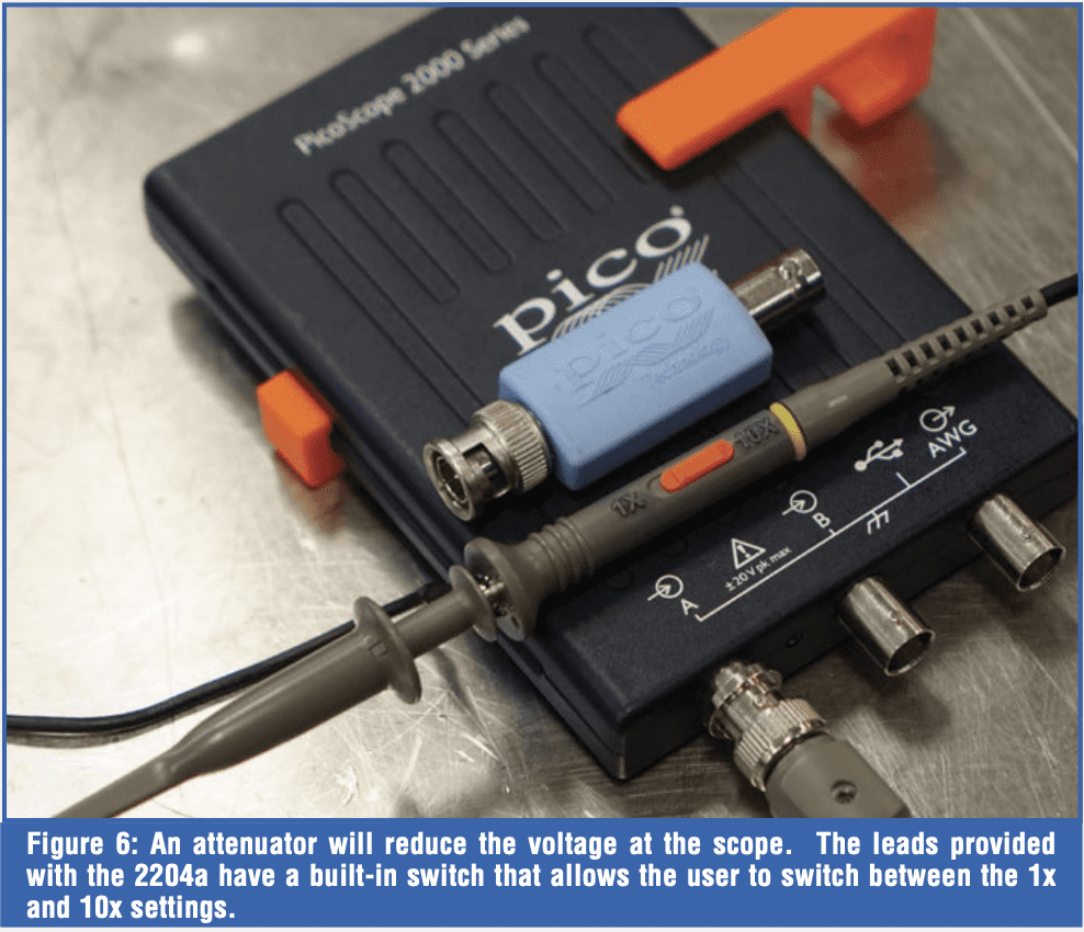 Notice in Figure 8, where I’m checking the ground connection between two separate channels on the scope, and it shows virtually no resistance. The grounds are common on many scopes, including the 2204a. How is this a problem? Well, imagine you are connected across a fuel injector or solenoid with one channel, and you’re connected to battery power and ground on the second channel. Since the grounds are common in the scope, you’ll effectively be providing a ground through the scope leads for the injector or solenoid. To be safe, it’s best to keep the scope grounds on the actual ground.
SAMPLE RATE
Make sure you monitor the scope’s sample rate. With the 2204a, if you have too fast a timebase, the sample rate drops off dramatically. A fast-switching signal might look sawtoothed and irregular (Figure 4). 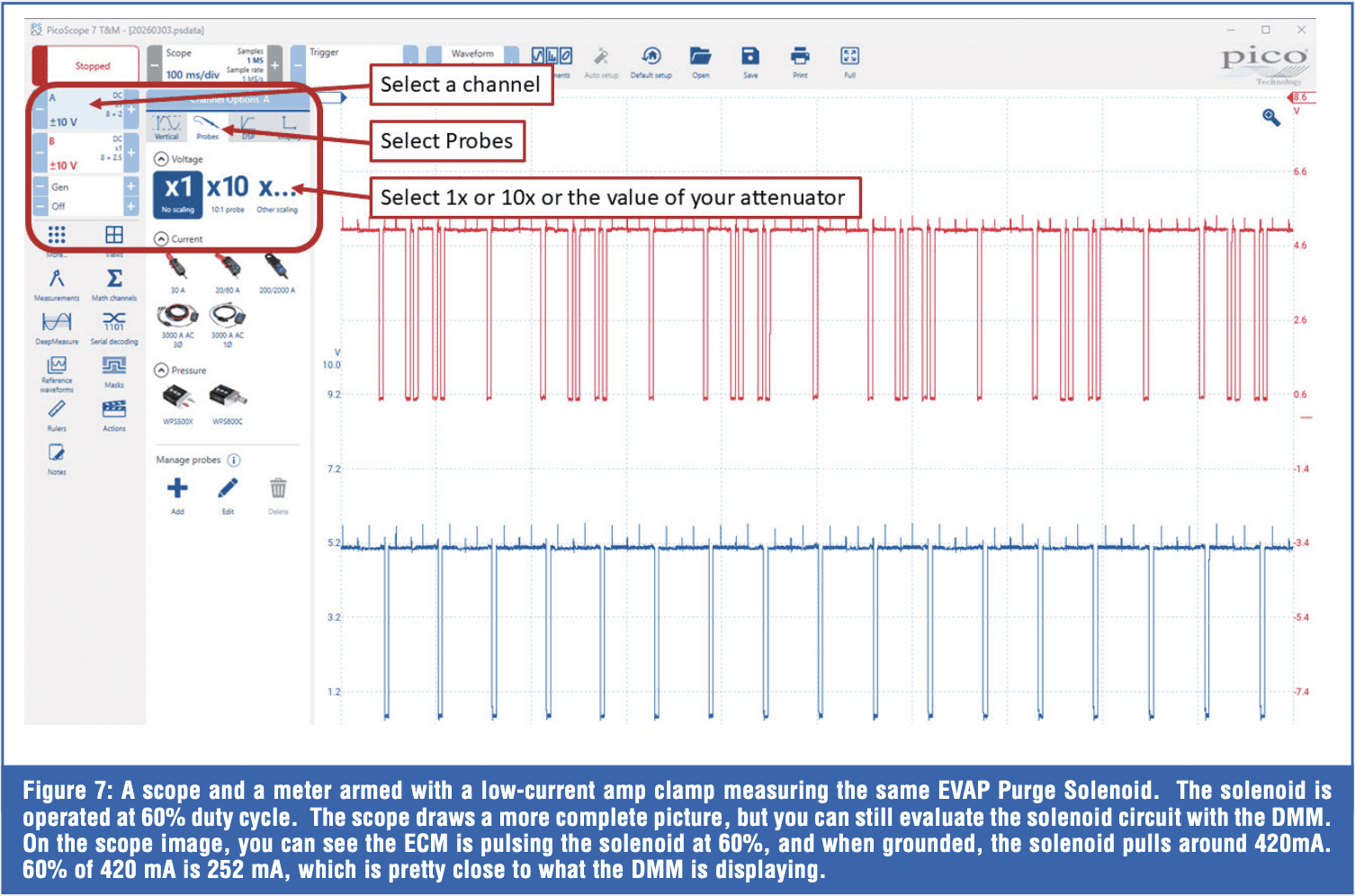 This is a drawback of the inexpensive scope, and that’s why you are best keeping the timebase higher, above the “progressive mode” setting mentioned earlier. Along those same lines, just because you can change the sample rate on the scope, it doesn’t mean the scope is capturing and displaying at that sample rate. The software will let you crank up the sample rate as high as you want, but the actual sample collection rate is limited by the hardware. Look for the samples and sample rate indicated in the timebase box to see how many samples are actually plotted. This is hardware-limited, so pricier scopes can sample at a much higher rate, even though very high sample rates aren’t always necessary.
CONCLUSION
Many technicians shy away from the DSO. It’s understandable because of the high costs associated with purchasing a scope, leads, adapters, amp clamps, ignition probes, pressure transducers, etc. 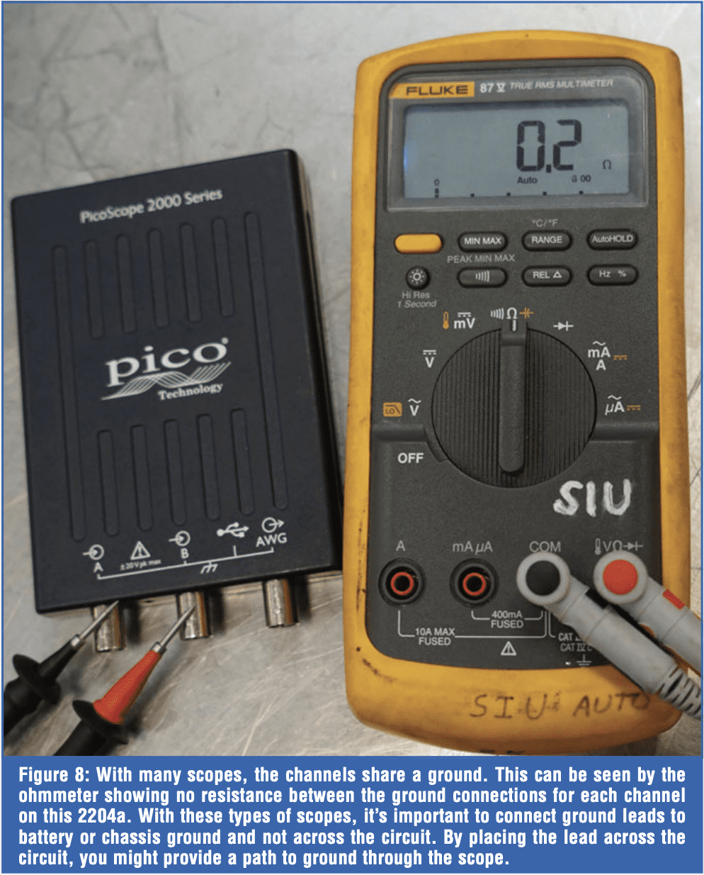 This is why I’m taking an approach that focuses on covering the fundamentals of DSO usage with an affordable scope. For most measurements, the 2204a works just fine, including:
- Fast Switching Sensors – crank, cam, magneto resistive, hall-effect, VSS, ABS, MAF
- Network – High and Low speed CAN, LIN, and others
- Actuators – Fuel Injectors, Solenoids
- Coils – Primary and Secondary
- Dynamic Tests – relative compression, pressures, amperage, NVH
Just about everything can be measured with the 2204a, but with that said, there might be a few tricks to get the ideal pattern. But that’s a topic for the next article, where we’ll dive into actual testing of sensors and components. If you are interested in this journey and want to take on the challenge of learning scope-based diagnostics, I’m in your corner. If you have any ideas, suggestions, or questions, please reach out to me at jeepster@siu.edu.


