
When dealing with engine and transmission issues, being able to “draw the line” between the two can drastically reduce diagnostic time. If a transmission isn’t shifting correctly on a vehicle with mass airflow sensor codes, this segregating decision can be relatively easy. In other cases the decision can be a bit tougher.
Mastering this diagnostic technique can often be the key to successful and efficient diagnosis. In this month’s article, we’ll explore a transmission-related issue; our goal is to draw the line between an electrical problem and a hydraulic/mechanical one.
The vehicle is a 2002 Dodge Ram 1500 with a 5.9 liter gasoline engine. The customer had only one complaint: The MIL was on.
The technician connected a scan tool and retrieved code P0740 — Torque Converter Clutch; No RPM Drop at Lockup. The tech proceeded with the diagnosis and determined the issue was an internal transmission problem. This shop doesn’t rebuild transmissions so they wrote an estimate for a remanufactured transmission from a reputable rebuilder.
The customer approved the repair and the technician replaced the transmission. The vehicle left the shop with no issues and the customer drove the vehicle from Chicago to Atlanta, pulling a trailer. When it got back to Chicago, it was due for an oil change, so the customer brought it back to the same shop for service.
While changing the engine oil, the technician noticed a transmission leak, so he made arrangements to fix the leak under warranty. The MIL wasn’t on and there were no diagnostic trouble codes stored.

The shop contacted the remanufacturer; they told the shop technician not to repair the leak; they’d send out a new transmission complete with a labor payment for R&R. The technician gladly complied and replaced the transmission a second time. The owner left the shop happy, only to return a week later; the MIL was back on.
The third visit to the shop revealed code P0740 was back. The technician performed some initial tests and informed the shop owner that the problem was probably internal… again.
The shop owner was a bit skeptical, so to avoid problems, they consulted an outside specialist.
Today you’re that specialist: Based on this vehicle history, would you replace the transmission again? Answering “yes” might solve the problem, but could there be a problem with the PCM not commanding the torque converter clutch to apply? Could it have a broken wire? Your task is to draw the line between an electrical problem and a hydraulic/mechanical one.
The first step is to do some research. A good starting point would be to search for applicable technical service bulletins. The search yields no useful results. Next, you’ll want to investigate DTC P0740 and system operation (figure 1).
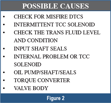 According to Chrysler service information, when the TCC is commanded on, the PCM expects to see an RPM drop because the TCC loads the engine. More information suggests possible causes, including multiple hydraulic/mechanical issues, but no mention of a wiring problem or a faulty PCM (figure 2).
The next step is to check the diagnostic trouble tree. The chart consists of twelve steps, none of which mention the possibility of an electrical issue. To make things worse, some of the steps include disassembling, inspecting, replacing parts, and retesting. Personally, I’d prefer to avoid these options unless they become absolutely necessary.
But there’s one step in the chart that you can use to your advantage: With the DRB-III, perform the TCC system test. During this test, the technician holds the brake pedal to the floor with the vehicle in gear. You then energize the TCC solenoid with the scan tool: The engine should stall if the system is working correctly.
In this case the engine doesn’t stall, indicating the TCC system isn’t working correctly. More importantly, this test allows you to exercise the TCC’s electrical controls. If you’re able exercise the system, are there many tests you can perform that aren’t indicated in the trouble chart?
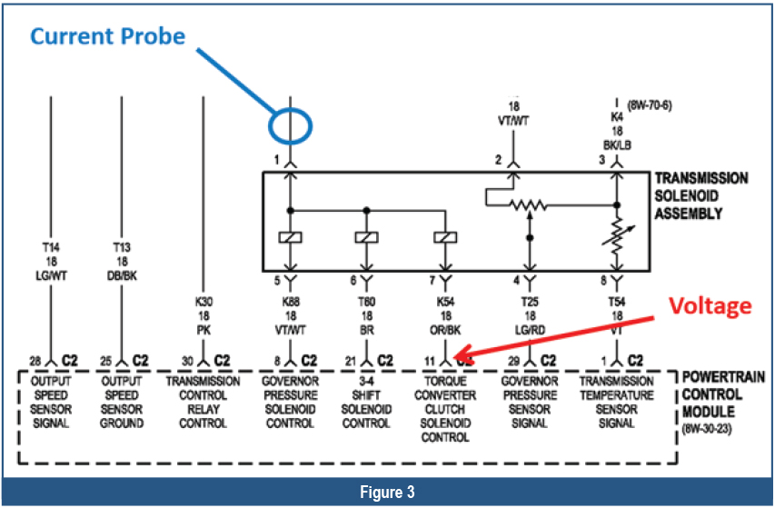 Using the wiring diagram as a guide, connect a scope between the TCC solenoid and its driver. The easiest place to make this connection is at the PCM (or JTEC-Jeep Truck Engine Controller) located just inboard of the right front fender (figure 3).
At the same time, connect a current probe around the voltage feed wire to the transmission solenoid assembly. The easiest access to this wire is at the transmission connector. The object is to observe both voltage and current for the TCC solenoid while commanding it on and off with the scan tool.
The scope captures the waveform shown (figure 4);
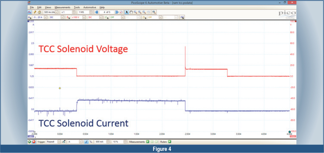
the red trace is TCC voltage. It begins at system voltage, because you’re connected to the ground side with the driver open. When the driver closes, voltage drops to 0 volts. The voltage drops all the way to ground and stays there, which indicates there’s no unwanted voltage on the ground side of the solenoid.
Once the driver in the PCM shuts off, the magnetic field in the solenoid collapses, creating an inductive kick (figure 4). So far the TCC circuit seems to be working correctly.
The second trace, (figure 5)
shown in blue, is the TCC solenoid current. Again you can observe the TCC driver turn on and off, just as in the voltage trace. But the current capture provides two more pieces of diagnostic information.
With the signal magnified, you can see a hump near the top of the ascending current slope. This hump occurs when the solenoid opens, inducing a small amount of voltage and current into the circuit. What this means is that the solenoid operated mechanically.
The second piece of information you can glean from this capture is solenoid resistance. Unlike using an ohmmeter to make this measurement, this test is dynamic and yields a much more accurate result because you’re measuring the solenoid circuit while it’s operating.
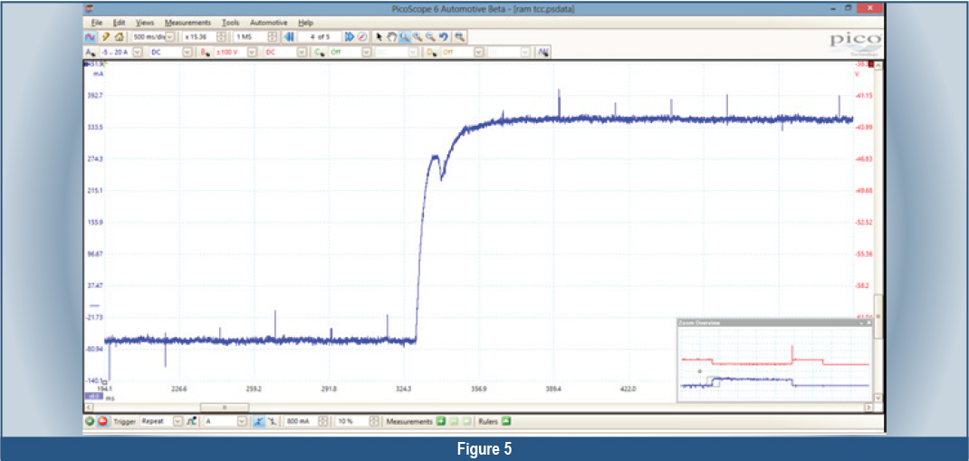
In this case, using Ohm’s Law and the current and voltage readings from the capture, you can calculate a solenoid resistance of about 29 ohms. Since the specification for the solenoid is 28-32 ohms, solenoid resistance is within specs.
So here’s what you know about the system: The PCM is able to command the TCC on and off. The TCC electrical circuit has integrity. The TCC solenoid is functioning as designed electrically. And the TCC solenoid is opening and closing mechanically. Given these facts, can you draw the line between an electrical and a hydraulic/mechanical issue?
The technician informed the shop owner that the TCC is functioning as designed electrically, and the problem must be inside the transmission. In this case, another remanufactured unit was installed and the issue was resolved. Regardless of the story used to illustrate the diagnostic technique, the point remains the same: Split a system in half and draw the line. By doing so, you can reduce the number of tests required to diagnose the issue and increase the accuracy of your diagnosis. There should be no reason to replace solenoid after solenoid based on a guess.