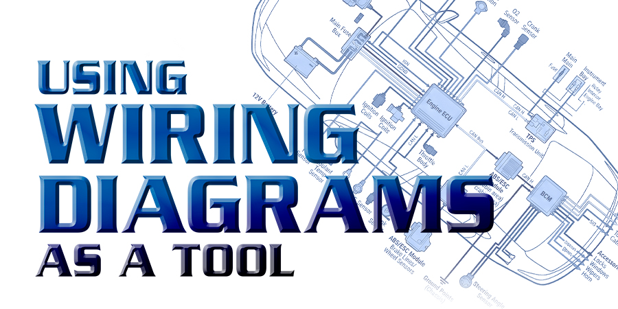
Wiring diagrams are one of the most important tools a technician can have. Wiring diagrams convert complex vehicle systems into readable logic. Wiring diagrams are essential for diagnosing electrical faults and can help prevent unnecessary part replacements. Wiring diagrams can be paired with component resistance specs to provide even more information.
Here are some things that a technician can do using a wiring diagram and component resistance specs:
- Identify test points before laying hands on the vehicle.
- Predict expected voltages
- Predict resistance
- Predict amperage
- Determine which test points are constant power, switched power, ground, switched ground, sensor signal, or communication.
- Determine whether the circuit uses shielding.
- Determine if voltage is AC, DC analog, or DC digital.
Wiring diagrams don’t always have all the information that you need. Voltages aren’t always listed on the diagram, so how do you know what to expect on each wire? OE diagrams from the manufacturer usually link the wiring diagram to the circuit description. The circuit description usually has the circuit details needed to predict the voltages on the circuit. Aftermarket diagrams usually don’t link to circuit details, so you have to search further in the service information to find the information. In some instances, it may not be available at all.
When the information isn’t available, we must use our experience and small details in the wiring diagram to predict the voltages. Some aftermarket companies redraw the diagram so mistakes can happen during the redrawing process. The OE factory wiring diagram can have mistakes, and every company that republishes it will carry them forward. For example, I found the injector circuit connected to the EGR circuit on a Cummins wiring diagram.
Sometimes the wire colors don’t match properly; in that case, try the previous year or the next year and see if it matches. Diagrams are drawn in the rest state where switches are open in most instances. When looking at the wiring diagram, find the component in question and work backward to identify the entire circuit. The diagram should indicate fuse amperage sizes; make sure no one has replaced the fuse with a higher or lower amperage rating or a circuit breaker.
Power starts at the top of the diagram, flows through the components, and reaches ground at the bottom.
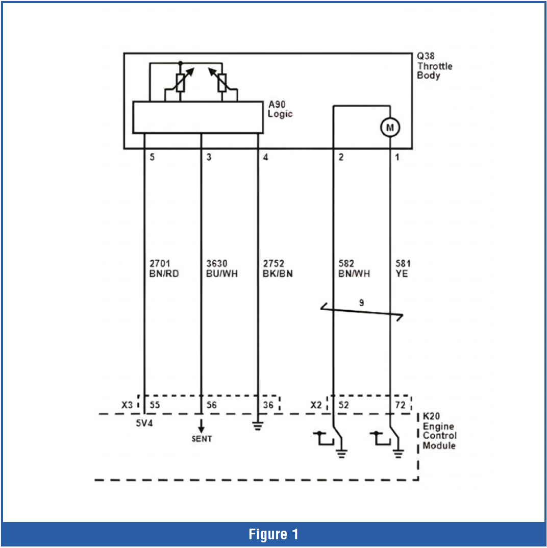 Here is an example of using a wiring diagram and predicting what type of voltage to expect. Figure 1 is a throttle motor assembly with two TPS sensors and a throttle motor built into one housing. Looking at the diagram, can you predict the expected voltages on each wire? What voltages would you expect from terminals 1 & 2? Terminals 1 & 2 operate the motor so you would expect 12-volt power on one terminal and ground on the other. The terminals will switch assignments depending on the throttle open or close command. What voltage do you expect from terminals 4 & 5? Terminal 4 will be ground, and pin 5 will be five volts. What do you expect from terminal 3? On early TPS sensors, this would be an analog voltage indicating the throttle position. This sensor, however, is a new smart sensor, so it is not an analog voltage. The diagram clearly shows two sensors inside but only one signal wire output. That means both sensors must report the throttle position on the same wire, terminal 3. How is that possible? The smart sensor makes this possible by incorporating a microchip that receives both TPS sensor voltages and converts them into a communication signal.
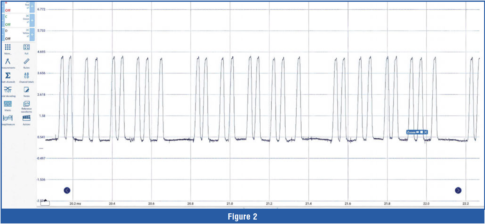
The two clues in the wiring diagram are the logic in the top box, which indicates a microprocessor, and SENT at the bottom on pin 56. SENT stands for single-edge nibble transition; it is a one-way communication protocol. The SENT signal embeds the two TPS sensor readings into one communication signal. The next step for the technician is to research the SENT protocol to determine what voltages to expect on the SENT signal wire. The SAE J2716 SENT protocol document calls for a signal above 4.1 volts to create a logic high and a signal below 0.5 volts to create a logic low. This information would indicate we should expect a 5-volt square wave. Figure 2 shows the waveform.
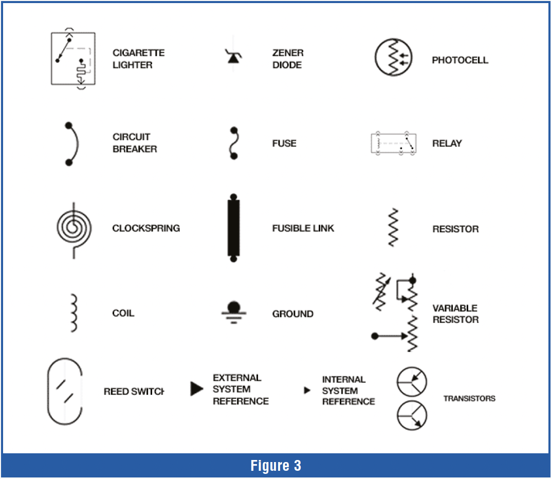
 It is imperative that the technicians can identify symbols used on the diagram. Symbols designate resistors, switches, solenoids, diodes, grounds, fusible links, transistors, bulbs, relays, and much more. Below is an example of symbols used in diagrams. (Figure 3). When troubleshooting a power-side fault, you must determine whether the power circuit is shared with other components. If those components are not working, the problem is usually a blown fuse or failed relay. If the other components are working, you may have a broken wire or bad connection to the failed component.
When troubleshooting a ground-side fault, you must determine whether the ground is shared with other components. If the other components are not working, it is probably the main ground contact point. If the other circuits are working, the problem is usually a broken wire or bad connection on that circuit only. Figure 4 shows an example of shared grounds.
 Now that we have covered some basics and set expectations, we will issue a challenge. The challenge is to determine the problem causing codes P0606 and P0562 on a 2022 Chevy Tahoe. P0562 code description: 12-volt starting and charging system code sets when lower-than-expected voltage occurs. P0606: control module performance. These two codes are only set in the Brake System Control Module (BSCM). P0562 is a low-voltage code; if the charging system had low voltage, that code should be set in multiple modules, but it isn’t. That assumption does not exclude the technician from performing a battery and charging system test along with a starting system test. Anytime a module has a low-voltage code, test the battery state of charge and state of health, alternator output, and the starting system. Should we perform a parasitic draw test? Yes or no, circle your answer to see if you are correct.
The two clues that should lead us to perform a parasitic draw test are the P0562 code, which indicates a 12-volt starting and charging system issue. The low-voltage code may have set during starting, which may indicate a weak or low-charged battery. If the battery voltage was low during start, it could point to a parasitic draw that drained the battery or a starter drawing too much current. Consider all clues when diagnosing a problem. Testing indicated no parasitic draw; the alternator passed all tests, the starter passed its test, but the battery failed.
We installed a new battery, erased the codes, and they came back. Where do we go from here? How about pulling up a wiring diagram of the BSCM and determining how many power wires it has (Figure 5)? Should we check the grounds since it is a power-related code? Yes or No (circle answer). 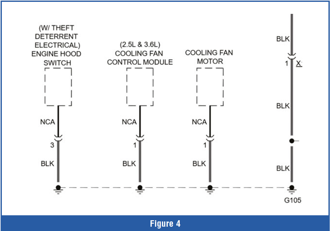 We should test ground as well because all voltages are measured from ground level, so an elevated ground could cause a problem measuring the voltage correctly. The wiring diagram is below. Can you identify the power and ground wires? There are three power wires: terminals 46, 14, and 9. There are two ground wires: terminals 1 & 30. We need to test for available voltage on the three power terminals. Can we back-probe the terminals at the BSCM with the key on and the engine running? That may be okay for pin 9 because it is an ignition feed, but pins 46 & 14 are 60-amp circuits. These two circuits require a load to perform a voltage drop test. Using a circuit load tester, we applied a 20-amp load to 45 & 14, and there was no voltage drop. Pin 9 had system voltage available when the engine was running, which probably means it’s okay.
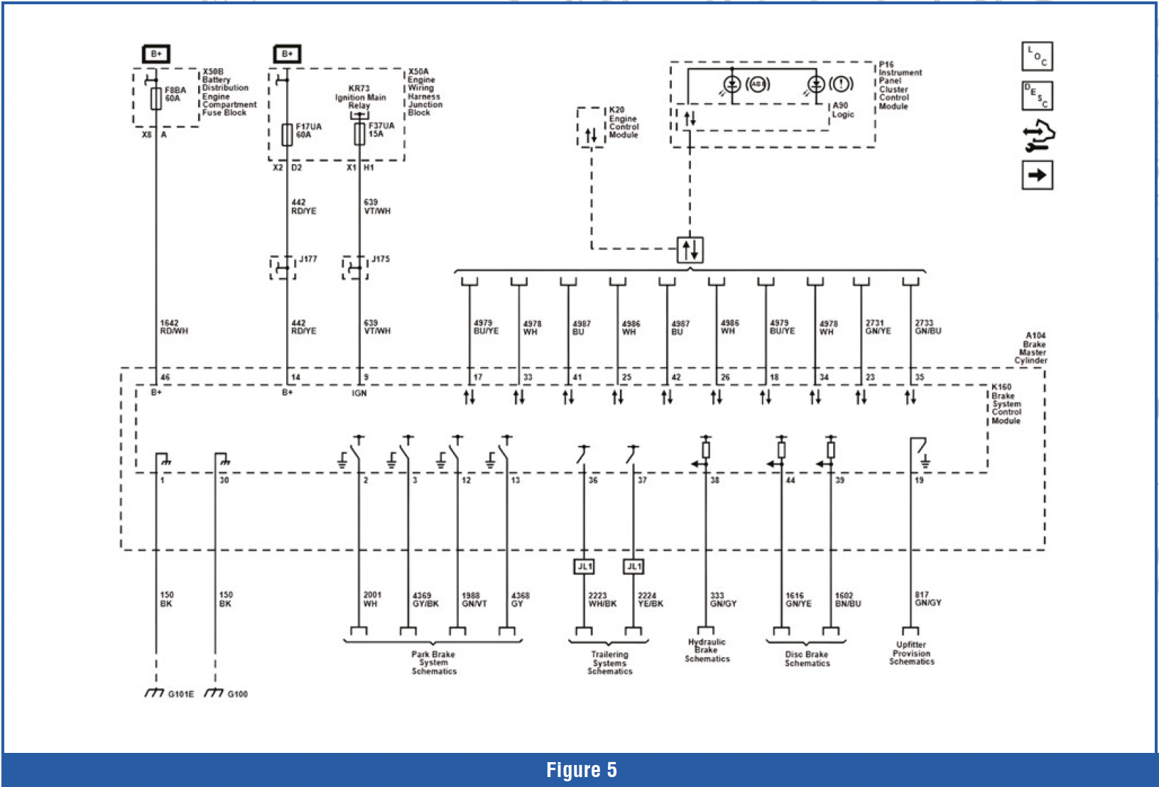 To be sure, we used the Load Pro tool and applied a small load to the circuit at pin 9. When we applied the load using the Load Pro tool, there was no voltage drop. Where do we go from here? The BSCM indicates a low-voltage concern, but we have tested all the power wires. Next, we tested the two grounds at terminals 1 & 30, and they passed testing as well. Where does that leave us? All the power and grounds pass. Is there something we haven’t tested? The answer is yes. One thing we can’t volt-drop test is the connection between the pins and the BSCM terminals. We removed the connector to the BSCM to look for corrosion and test pin fitment.
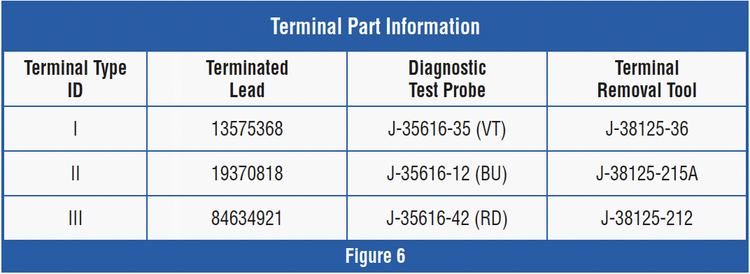 There was no visible corrosion. How do we test for pin fitment? First, we must identify the correct testing tools. GM’s service information identifies the removal tool if needed and the drag test tool’s part number. (Figure 6) We performed the drag test and found pin 9 failed the test and pin 46 was marginal. The problem was pin fitment on 9, and possibly on pin 46. Was the code helpful? Yes, it pointed to a low voltage problem. Was the wiring diagram helpful? Yes, the diagram indicated which terminals were power and ground. When testing circuits using a wiring diagram, it is easy to get confused about what to expect voltagewise; it may help to power-flow the diagram. Power-flowing a diagram simply means tracing the circuits with a specific highlighter color. Here is an example of colors used:
- Red-power all the time.
- Green-permanent ground
- Yellow-switched ground
- Orange-switched power
- Blue-analog voltage
- Purple-communication signal
After color-coding all the circuits, it becomes obvious what to expect when you back-probe the circuit; just refer to the highlighted color you used. We have been power-flowing circuits for years, and it helps reduce confusion.
That is all we have time for in this article; we may revisit wiring diagrams in the future.