Engines and transmissions have typically shared the vehicle’s cooling system. Cooling systems on older vehicles were very simple; they had one mechanical water pump, one radiator, and one thermostat. Modern cooling systems can be very complex. We will discuss a few of these complexities found on modern vehicles. There may be multiple cooling systems on the same vehicle, with separate mechanical and electric water pumps and separate radiators. Electric thermostats are common on some vehicles, and some vehicles have multiple thermostats with different opening temperatures, while other vehicles have deleted the thermostat altogether.  Multi-position coolant valves have been added to distribute the coolant to different components. Cooling system pressures and temperatures may vary drastically between the separate systems. Scan data and codes have been added to cooling system diagnostics. There are new drain-and-refill procedures that may require a scan tool. There are component relearn procedures that require a scan tool. Some manufacturers may disable the water pump during certain conditions. BMW does this by using a friction pulley. The friction pulley engages & disengages the crank pulley and water pump pulley. A stepper motor controls the position of the friction wheel (figure 1).
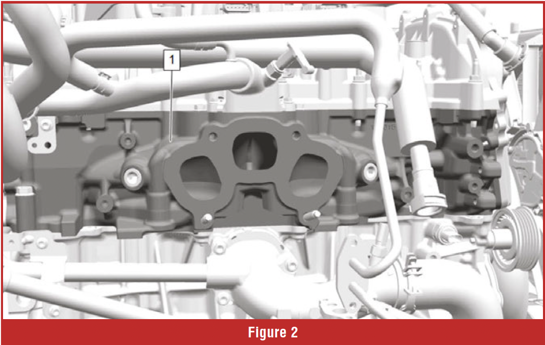
![]() Complete thermal management of the engine and transmission is the new goal. That means we not only need to cool components down, but we may also need to warm them up. Toyota heats the coolant with an exhaust heat recirculation system that routes it to an exhaust-mounted valve; the GM 2.7 Turbo model has an integrated exhaust manifold in the cylinder head. Both systems allow the coolant to be warmed up via the hot exhaust gas (figure 2).
Complete thermal management of the engine and transmission is the new goal. That means we not only need to cool components down, but we may also need to warm them up. Toyota heats the coolant with an exhaust heat recirculation system that routes it to an exhaust-mounted valve; the GM 2.7 Turbo model has an integrated exhaust manifold in the cylinder head. Both systems allow the coolant to be warmed up via the hot exhaust gas (figure 2).
GM 2.7 routes the warmed-up coolant to the engine oil cooler, passenger compartment, and transmission cooler. The hot coolant warms the engine and transmission oil, so the components reach operating temperature faster.
 The GM 2.7 turbo gas engine and the 3.0 Duramax have had the thermostat deleted and a rotary coolant valve assembly installed. Rotary coolant valves vary slightly depending on year and RPO code. The rotary coolant valve we chose for this example is from a 2021 1500 pickup with a 3.0 Duramax RPO code LM2. The rotary coolant valve replaces the traditional thermostat and handles coolant distribution. This coolant valve has a high failure rate and an extended warranty.
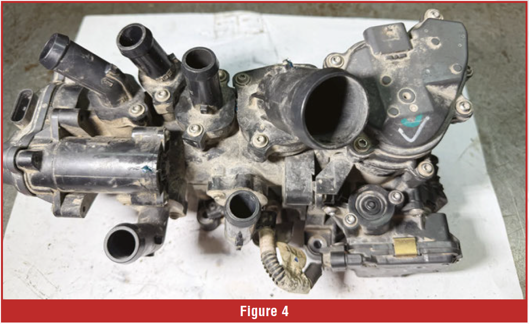
Let’s explore how sophisticated this coolant valve really is and the most common failure it can experience. The coolant valve’s backside bolts to the block at the two ports (figure 3). There are 6 more ports on the rotary coolant valve (figure 4). Inside the housing reside the flow control valve, the block rotary valve, and the main rotary valve. The three rotary valves are positioned by three DC motors. 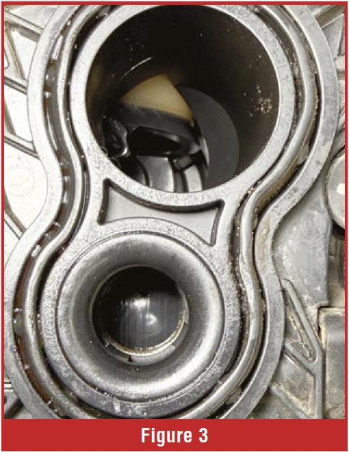 The three DC motors are bi-directional and are controlled by the ECM. The Wiring diagram (figure 5) shows the block rotary valve Q97B has three wires. A power wire on pin 3, circuit 5293, a ground wire on pin 2, circuit 4450, and a LIN bus wire on pin 1, circuit 2732. The block rotary valve motor has a built-in microprocessor that communicates with the ECM over the LIN bus to control motor direction and motor position. The microprocessor is shown in figure 6.
The microprocessor has two tension terminals that plug directly into the motor as shown in the figure. The motor employs a metal worm gear. The worm gear meshes with a plastic worm wheel. The worm wheel is part of a drive shaft with a plastic worm gear at the other end. The driveshaft worm gear mates with the gear that is attached to the rotary valve. The gear train can be seen in figure 7. A common failure with this design is plastic gear failure. The worm gear and worm wheel mating surfaces fail, rendering the block rotary valve inoperative. Wear in this area is shown in figure 7. To inspect the gears, simply remove the spring-loaded retainers and pop the plastic top off the motor.

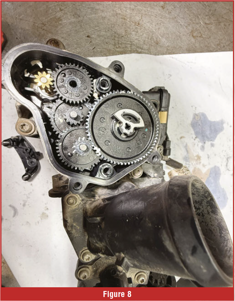
 The block rotary valve controls flow from the block to the head. When a gear failure occurs, the ECM will set code P01098, which is the engine coolant valve position sensor minimum stop performance. When this code sets, it typically derates the engine power. The other two motors located on the coolant valve have built-in microprocessors but employ a totally different gear design. The motor gear is a small straight-cut metal gear that uses a series of straight-cut plastic gears to provide gear reduction for opening and closing the additional rotary valves. The straight-cut gear reduction design shown in figure 8 does not suffer the same gear failure discussed previously.
Next, we will look at port assignments. We have 6 external ports bolted onto the coolant valve (figure 9). Each port has an O-ring that seals the port to the coolant valve assembly. Port 1 controls the flow of coolant from the block to the radiator. Port 2 is always open and controls coolant flow to the EGR, turbo, and heater core. Port 3 controls coolant from the EGR and turbo. 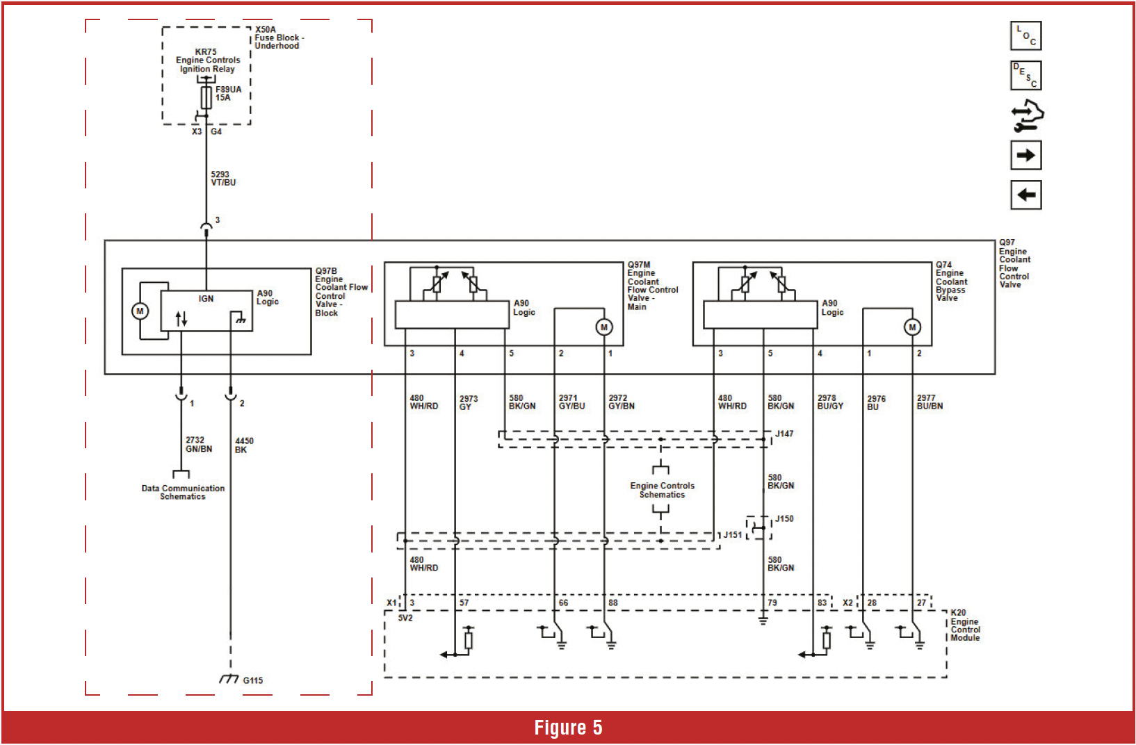 Port 4 is the cold feed from the heater coolant pump. Port 5 controls coolant flow to the engine and transmission oil coolers. Port 6 is the bypass port for the system.
When the driver demands max heat in the passenger compartment, coolant is shut off to the radiator. The heater circuit is fed by a combination of cylinder head, EGR valve, and turbocharger coolant, heated to maximize coolant heat transfer from the engine to the passenger compartment. The hot coolant can also be sent to the engine oil and transmission coolers to warm the fluids quicker. Bringing the engine oil and transmission fluid up to temperature quicker reduces wear, friction, and increases fuel mileage.
 There are five temperature sensors that provide feedback to the ECM. The temperature sensors are as follows: Engine cylinder head metal temperature sensor, Engine inlet temperature sensor, Engine outlet temperature sensor, Engine oil temperature sensor, Radiator outlet temperature sensor. All three coolant valve motors have built-in position sensors that report rotary valve positions, enabling proper coolant distribution. Due to built-in position sensors, when a new coolant valve is installed, a relearn process must be performed with a scan tool.
The rotary valves in the coolant valve assembly must be cycled during a drain-and-refill. The scan tool will activate an automatic coolant service fill procedure. 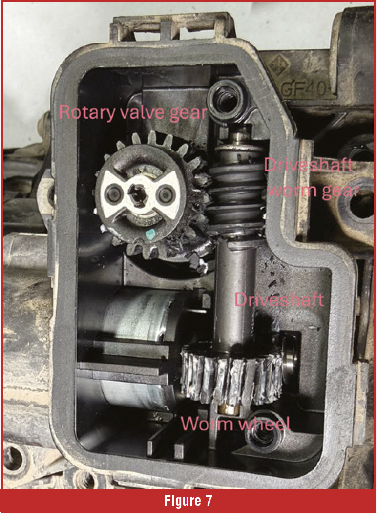 During the refill process, the coolant rotary valves will be cycled to help remove air from the coolant fill.
The coolant valve at engine shutdown opens the port that directs coolant to the radiator; this permits coolant to flow by gravity through the system. The ECM also performs a diagnostic check of the coolant valve after shutdown.
Ford’s 6.7 Ford PowerStroke uses a totally different approach than the GM 3.0 in-line Duramax engine. The 6.7 PowerStroke uses two separate cooling systems labeled primary and secondary. There are separate belt-driven mechanical water pumps, radiators, degas bottles, and four thermostats.
 The primary cooling system, also called the high-temperature cooling system, handles the engine block, heads, engine oil cooler, turbo, and EGR. The secondary cooling system is also referred to as the low-temperature cooling system; it handles half of the EGR cooler on early models, transmission cooler, charge air cooler, and fuel cooler.
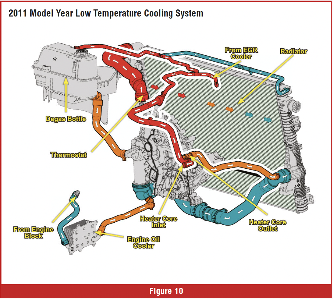
The primary system runs under a higher pressure; the degas bottle cap is rated at 21 psi (figure 10). The secondary cooling system runs at a much lower temperature and pressure; the cap is rated at 5 psi.
The secondary cooling system’s radiator sits in front of the primary radiator; it is a crossflow design that is split horizontally. The secondary radiator is unique in that it has one inlet and two outlets, with thermostats mounted on each side of the radiator.
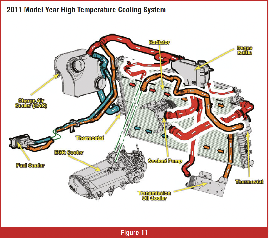
The secondary cooling system is a two-stage design. The first stage is the upper 2/3 of the radiator; it exits the right side of the radiator. The first stage cools half of the EGR cooler and transmission cooler. 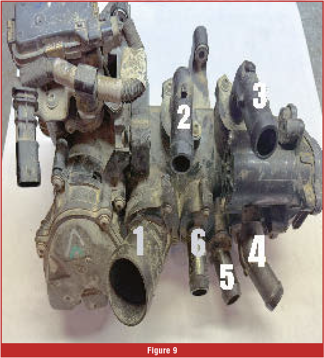 The second stage, or lower 1/3, of the radiator, exits on the left side and cools the charge air cooler and the fuel cooler. The right side of the radiator houses the first stage thermostat that opens at 130-140 degrees. The left side of the radiator houses the second stage thermostat that opens at 68 degrees (figure 11). Even when the thermostats are closed, some coolant bypasses the radiator, creating flow through the coolers. When the thermostats are open, all the coolant flows through the radiator.
The first stage of the secondary cooling system, running at 130-140 degrees Fahrenheit, can keep the transmission fluid temperature from overheating far better than the primary cooling system, operating at 190-220 degrees Fahrenheit.
 Transmission fluid works well at temperatures between 160-200 degrees. When transmission fluid is cold, it gets thicker, slows hydraulic response, and can cause harsh or delayed shifts. When transmission fluid gets too hot, it starts to break down, increasing wear and causing pump cavitation. ATF oxidation accelerates dramatically with heat and lowers the ATF life expectancy. Cooling systems have become very complex, with complete thermal management systems that handle all the cooling and heating needs of engine- and transmission-related components. When faced with transmission temperature-related concerns, it is necessary to take the correct steps to diagnose the problem.
Step 1: Identify how many cooling systems are on the vehicle.
Step 2: Determine if cooling systems are connected.
 Step 3: Identify how many valves are in the cooling system.
Step 4: Identify how many thermostats are in the cooling system and thermostat locations.
Step 5: Determine if valves need to be in a specific position to perform coolant service.
Step 6: Identify all components, component locations, and any unique features in the cooling system.
Step 7: Check for cooling system-related codes.
Step 8: Perform any relearn procedures that need to be performed after component replacement.
This article is just a reminder of how a simple system, such as the cooling system, has become very complex in modern vehicles, and why we need to do some research before diving in.