What is inductive current analysis? It is the ability to look inside a circuit and view work being done. In the electrical world, work is often performed by inductors. Inductors are coils of wire that store energy in a magnetic field. Why is storing energy in a magnetic field important? The energy stored in a magnetic field can be used for many things, like creating a spark for the ignition system, opening a fuel injector, or moving the pintle inside of a shift solenoid. Magnetic fields can also be used to operate a relay, opening and closing a circuit (figure 1).
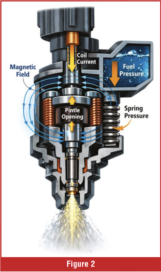
The strength of the magnetic field must be matched to the work being performed. The magnetic field must be strong enough to perform the work in the circuit, for example, moving the pintle in an injector. The injector pintle must overcome spring pressure and fuel pressure to open. A GDI injector pintle must overcome much higher fuel pressure than a port fuel injector; therefore, the magnetic field must be much stronger (figure 2).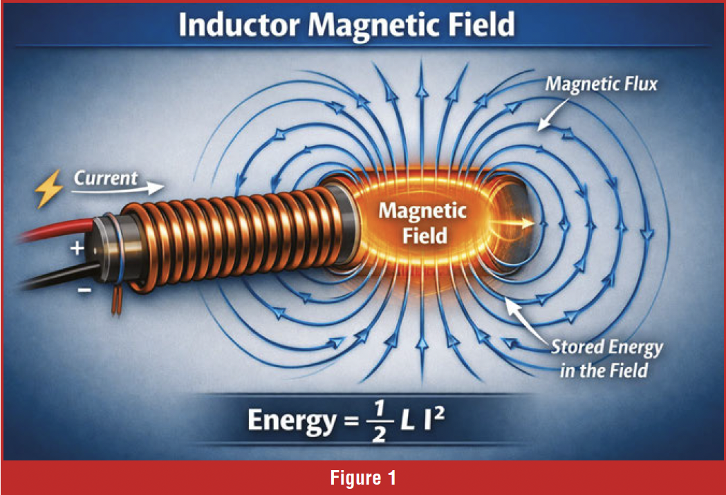
The magnetic field strength is determined by the number of turns in the coil, the size of the wire, the core material, and the voltage. All these factors are considered when engineering the component. The technician has no control over these factors; however, the technician can measure the magnetic field to ensure the component is working properly.

How do we measure the magnetic field? The industry created amp probes years ago to measure a circuit’s magnetic field, which corresponds to how much amperage is flowing in the circuit. The amp probe became very useful when it could be attached to an oscilloscope and display an amperage waveform. The magic of the amp probe lives in the jaws. Inside the jaw of an amp probe is a Hall effect sensor.
 The Hall effect sensor senses the magnetic field and produces a proportional voltage signal; the resulting voltage signal is sent to your oscilloscope and can be viewed on the screen. It is important to understand that the proportional voltage produced by the low-amp probe may or may not be calibrated to your scope’s amperage scale. The low-amp probe that came with your scope is calibrated to the amperage scale on your scope. If you are using a generic low-amp probe with your scope, you will need to perform a calculation and use the millivolt scale to measure amperage accurately.
An example of this would be using a PDI low-amp probe with a conversion factor printed on it. The first setting is one millivolt equals 100 milliamps. The second setting is 1mv equals 10 milliamps (figure 3).
You can use the millivolts scale on your scope and apply the conversion factor to get accurate amperage measurements. Most low-amp probes require zeroing before placing them around a wire and making a measurement. Some low-amp probes, like the Pico smart amp probe, self-zero when connected to the scope. The smart low-amp probe is powered by the scope, which is how it can self-zero. If your low-amp probe is battery-powered and not powered by the scope, it will need to be zeroed before connecting to the circuit.

Using the low-amp probe on inductors such as transmission solenoids, ignition coils, and injectors requires some knowledge of charge time constants. It takes time to charge a coil of wire; it does not happen instantly. Solenoids do not drop amperage instantly when turned off. The transient behavior is characterized by the time constant. A time constant is the time that it takes to reach 63% of the final value or decay to 36.8% of its initial value when turning off. The time constant can be calculated by knowing the inductance (L) and the resistance (R). 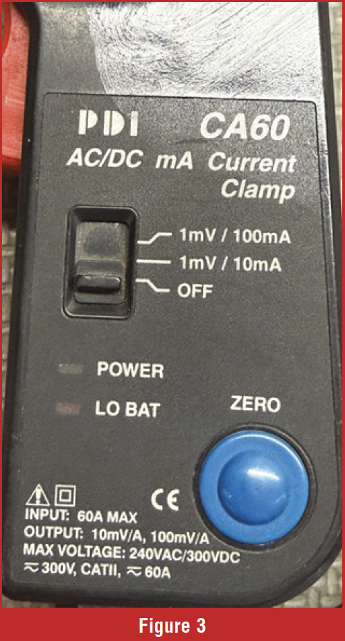 The formula for calculating the time constant is T = L/R. A larger inductance results in a longer time constant because the current takes longer to change. Reducing the resistance will result in a longer time constant because a higher amperage will be achieved.
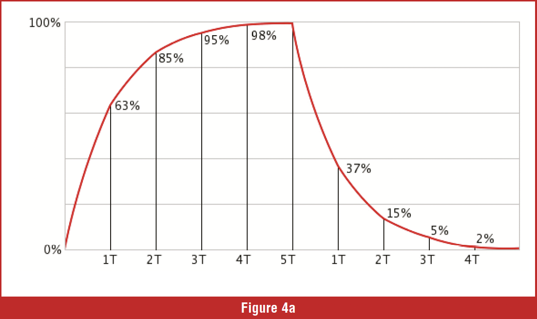
Understanding the charge time constant helps predict how long the charge time should be for the solenoid you’re testing. When the coil of wire starts to take on charge, it develops an opposing counter-electromotive force (CEMF) that opposes the input voltage. CEMF increases as the windings take a charge, slowing the current flow. CEMF will cause a solenoid amperage waveform to form a ramp that can be divided into five time constants. It is important that the charge ramp is gradual; if the ramp travels straight up at the beginning, that indicates the coil has shorted windings. Time constant one: amperage will reach 63%, time constant two: amperage will reach 86%, Time constant three: amperage will reach 95%, time constant four: the amperage will reach 98%, and time constant five: amperage will be at 99% (figure 4A).
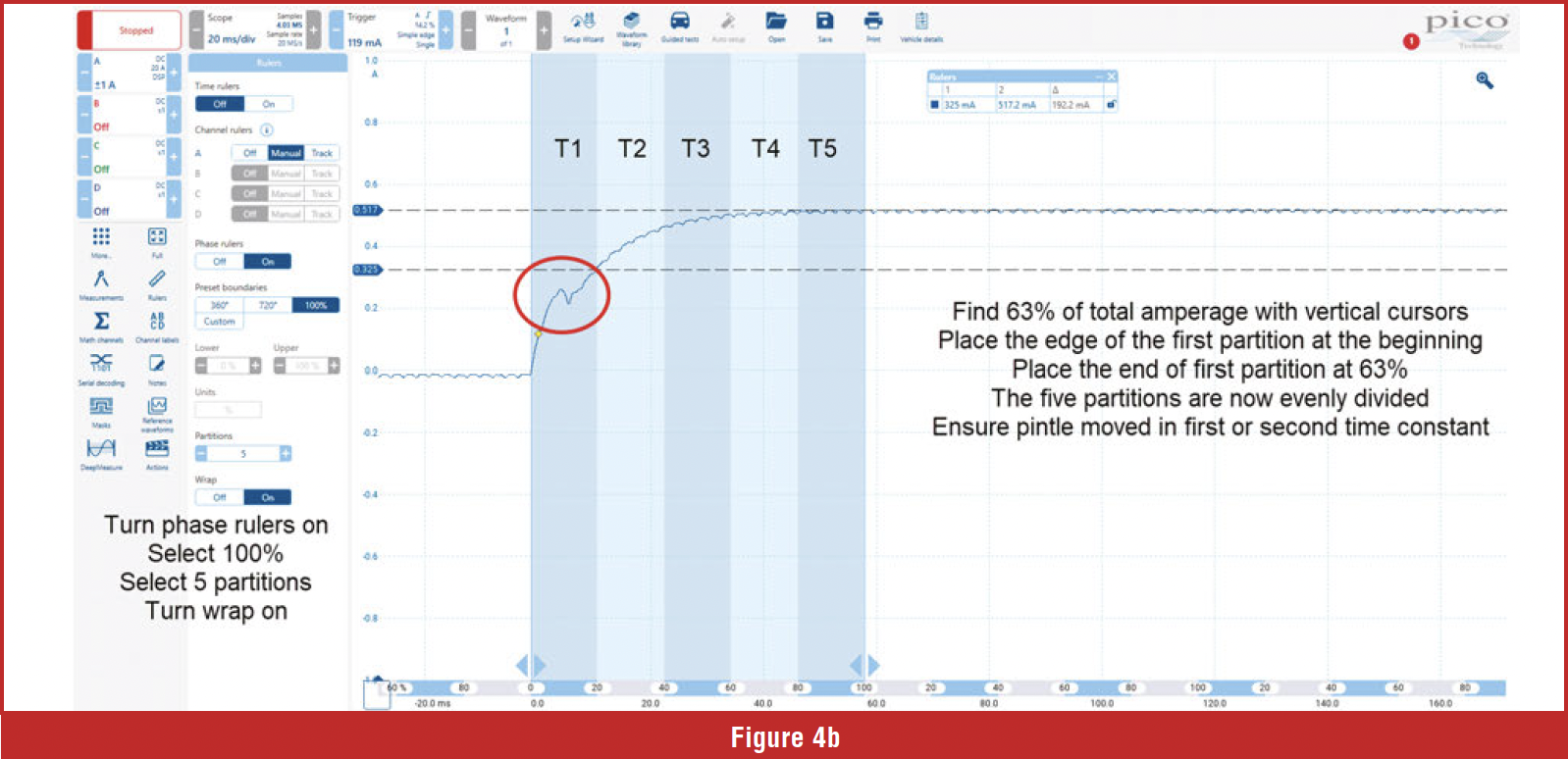
The pintle inside the solenoid should move during the charge ramp. The pintle movement can be seen in the amperage waveform. The pintle movement will cause an irregularity or a hump in the charge ramp. Most solenoids will experience pintle movement at the end of the first time constant or somewhere in the second. If the pintle does not open until the third, fourth, or fifth time constant, the pintle is opening late. Let’s review how to set the Pico scope to five time constants and check the pintle opening (figure 4B).
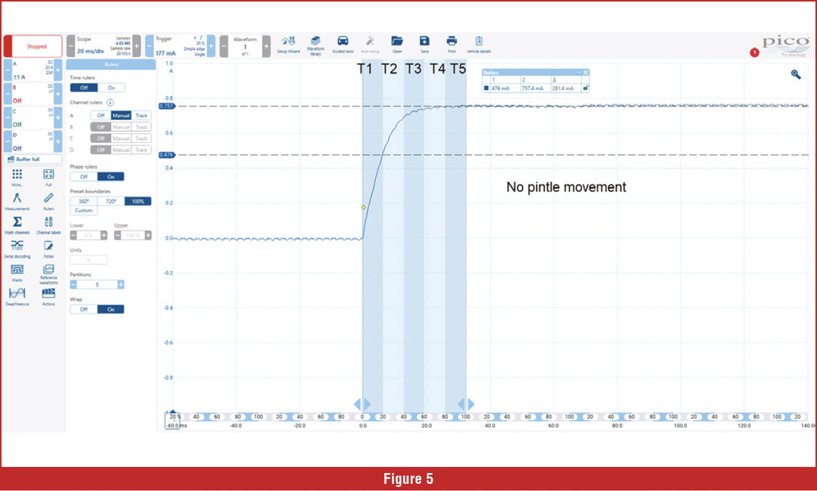
The pintle opened in figure 4B during the first time constant. The next waveform is a shift solenoid from a 4T65E that would not shift into second gear. We have applied the time constants to the waveform (figure 5). The waveform has a nice smooth ramp, which indicates the windings are in good shape, but the pintle hump is missing. Electrically, the solenoid is good, but mechanically the pintle is stuck. The stuck pintle is the cause of the no upshift.
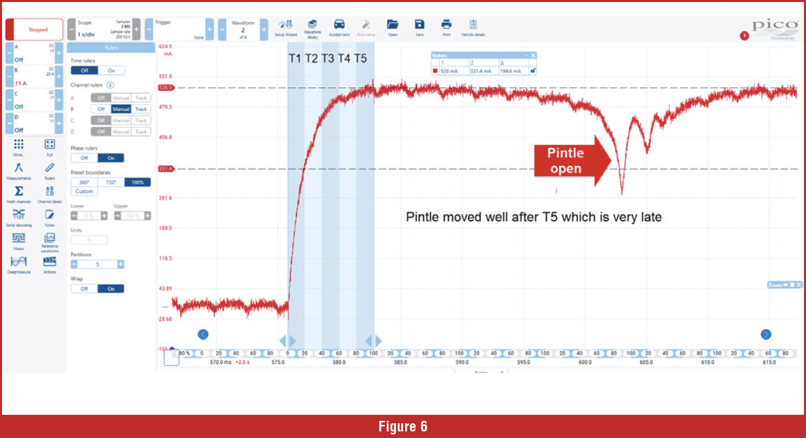
 The next waveform is from a vehicle with an EVAP leak code. The system was sealed by turning on the EVAP vent solenoid. The system was smoke-tested, and the leak was traced to the EVAP vent solenoid. We placed a low-amp probe around the power wire to the EVAP vent solenoid and retrieved a waveform. If we analyze the waveform, we can see the pintle did not move until well after the time constant of 5. The pintle is very late, indicating it may be dirty and unable to move properly; this is why the vent solenoid could not seal properly (figure 6).
The voltage control side can be viewed along with the amp probe. If we include the voltage waveform, we can analyze the condition of the control module driver. The driver pulls the ground side of the circuit to ground.
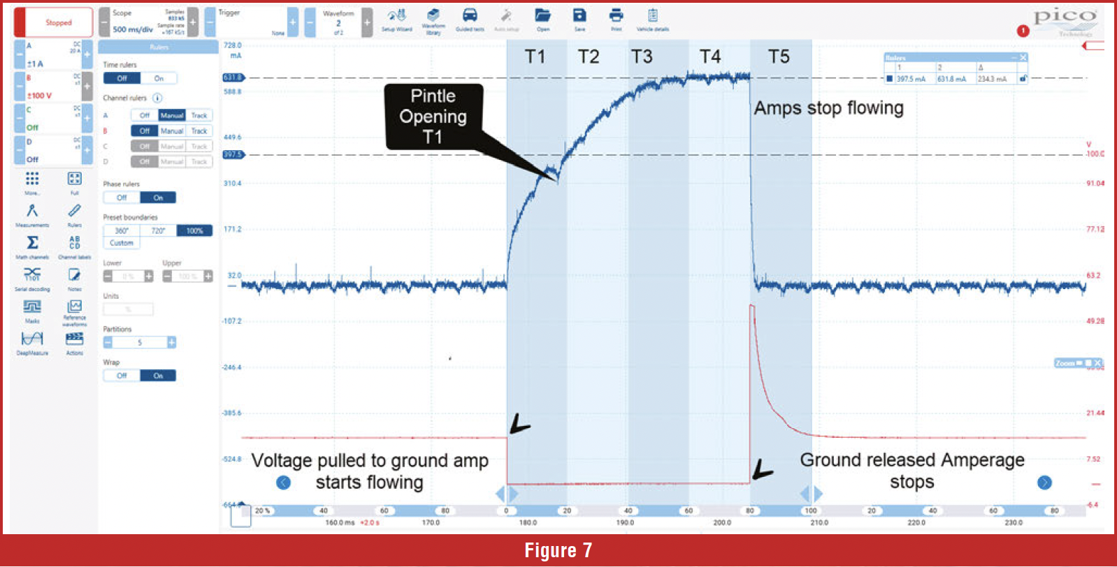
Many solenoids operate at constant power, and the ground is used for control. Back-probe the ground side and set your lab scope scales to voltage. A 20-volt scale is adequate. When the control side is grounded, amps should start to flow; when the ground is released, the amperage should cease to flow. The ground voltage waveform should pull straight to ground with no hash or stair steps. If a lot of hash or stair steps are present in the ground pull-down section, suspect a bad control module driver (figure 7).
You can also check the ability of the driver to release the ground. Some drivers bleed current during the release phase; if the control module driver bleeds current when opened, the amperage will not drop properly.
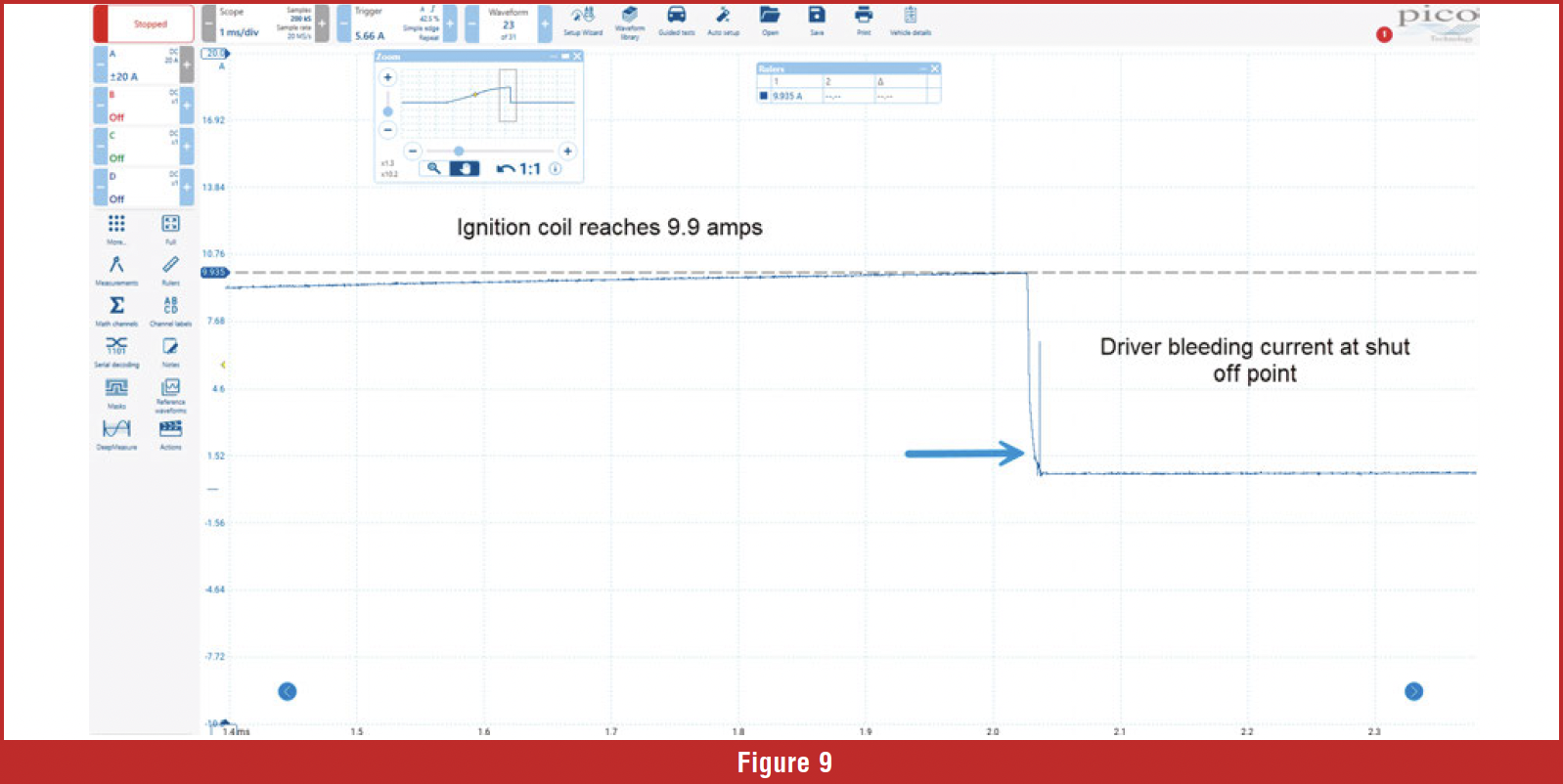
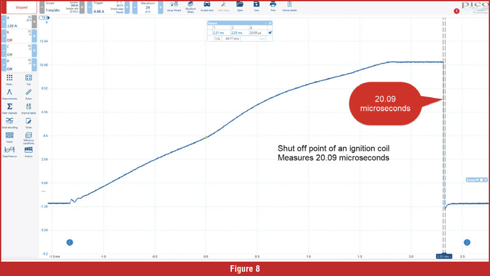
We can view the driver’s ability to open the circuit on the trailing edge of the amperage waveform, as seen in figure 8 of an ignition coil waveform. The next waveform is from an ignition coil with the control module driver in the early stages of failure (figure 9). The driver cannot open the circuit cleanly. The driver opens but continues to bleed a small amount of current. If the driver doesn’t open cleanly on an ignition coil, the magnetic field built up in the primary windings cannot collapse properly into the secondary windings. This failure will cause a weak spark or, in some cases, no spark in the secondary, resulting in a misfire. If this type of failure occurs on a transmission shift solenoid, the solenoid will stay on too long, causing a slight shift timing problem.
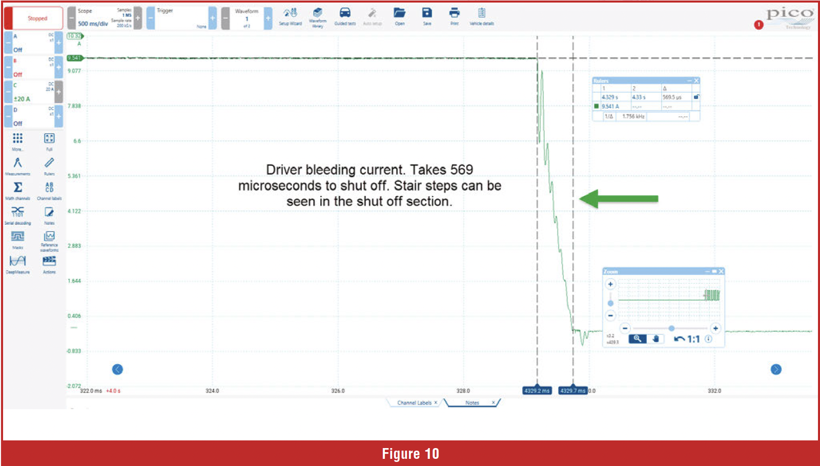 Let’s look at one more bad driver bleeding current; this waveform shows an ignition coil operating at 9.5 amps. The shut-off section has small stair steps, which are abnormal. An ignition coil should stop flowing amps in 15-50 microseconds, but this driver takes 569 microseconds to shut off, resulting in no spark from the secondary (figure 10). Let’s look at one more common issue with inductors: the coil of wire in the inductor expands and contracts with heat and is also exposed to vibration. The movement of the wire can rub the insulation off the wire, creating turn-to-turn shorts. If the inductor is experiencing this condition, it will weaken the magnetic field. If the magnetic field is too weak, it may not provide enough energy to open an injector, move the pintle in a shift solenoid, or create a spark from an ignition coil.
 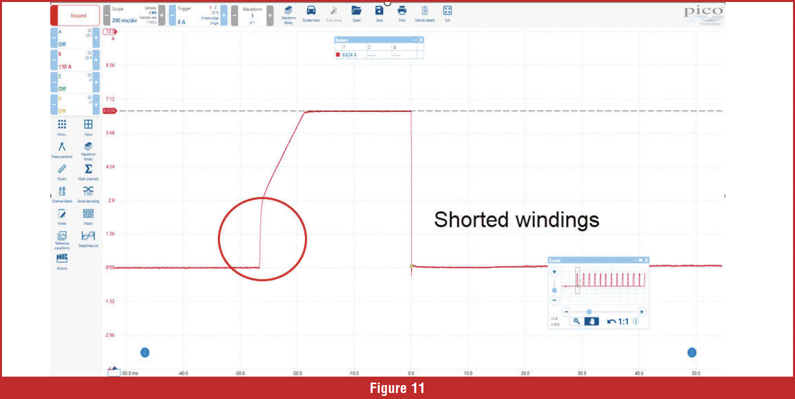 Turn-to-turn shorts can be seen at the beginning of the charge ramp of the amperage waveform. If the windings have turn-to-turn shorts, the amperage will rise abruptly at the beginning of the ramp. The ramp should start out gradual and not go straight up. Figure 11 is an example of shorted windings. In summary, inductive current analysis can be very helpful in determining the health of the windings in an inductor, checking whether the component meets the expected amperage, verifying pintle movement, and checking the condition of the control module driver.