There was a time when Dennis Madden walked around the office and asked everyone to identify markings on a ruler. You should have seen the chaos that ensued. People got the 1/2 and the 1/4, but when it came to the 1/8, 1/16, 1/32, and 1/64, let’s just say that eyes were glazed over. Understanding your measuring tools can help you understand how and why transmissions last longer when you build them correctly and your measurements are on spec. Let’s take a look at some of these most common measuring tools.
THE VERNIER CALIPER
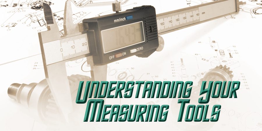
The Vernier caliper is the most common measuring device and probably the most versatile one. It can measure inside and outside diameters, heights, and depths and comes in digital form. Before we get too far into this, I’m going to make a simple suggestion to you: Buy a digital caliper (Figure 1).


Fixing transmissions is critical work. Some may say it’s rocket science, but it doesn’t have to be. You’ll probably be close enough if you’re within a thousandth of an inch — or a hundredth of a millimeter. A digital caliper will give you that level of accuracy without forcing you to spend a lot of time learning to interpret a convoluted scale that’s too tiny to be read without a magnifying glass.
A digital caliper gives you a simple digital readout, in either inches or millimeters, at the press of a button. No more trying to interpret the scratches on a scale or adding the numbers: Just read and go. Of course, if you prefer to learn, even if it isn’t something they’re necessarily going to use. For them, we’ll look at how to use all of the more common types of calipers and micrometers. We’ll start with calipers, beginning with the basics common to all calipers.

There are several parts common to most Vernier calipers (Figure 2). You’ll need to know these terms so you’ll understand the explanations for how to use them.
- Outside Jaws — for measuring the outer diameter of a component.
- Inside Jaws — for measuring the inside diameter of a component.
- Depth Probe — for measuring depth.
- Main Scale/Fixed Scale — usually provides measurements in Imperial (inches) or Metric units.
- Vernier Scale/Moveable Scale — a slider that indicates the measured size on the scale.
- Adjustment Roller — allows for easy movement of the jaws; not all calipers have this.
- Locking Screw/Lever — locks the caliper jaws in place to make it easier to read the measurement.
Before you begin a measurement with any caliper or Micrometer, your first step is to zero it. This is an important step to assure accuracy and should be repeated before each measurement.

You can also use the zeroing feature to measure the difference between two components.


With the jaws measuring the first component, zero the caliper. Then, measure the second. The measurement on your caliper is the difference between the two components. Here’s how to zero your caliper:
- Open the caliper.
- Slide it gently back to the fully closed position. You may have to do this a couple of times to be sure it’s closed all the way.
- Check the measurement on the scale. With the jaws fully closed, the scale should read zero.
- To zero a digital caliper, just press the “zero” button (Figure 3).
To zero a dial caliper, loosen the locking screw and rotate the dial until the needle is pointing to zero (Figure 4). Dials such as these are subject to parallax errors. That is, slight errors created when you view the dial from different angles. To avoid parallax errors, always keep the dial squarely in front of you when reading the measurement; never read it from an angle.
 To zero a standard caliper… well, you can’t; at least, not for any I’ve ever seen. All you can do is compensate for the inaccuracy. Check how much it’s off, then subtract that amount from (or add it to) your final measurement to get an accurate reading. Let’s start measuring!
OUTER DIAMETER
Outer diameter is probably the most familiar use for a caliper. You use the outside jaws to measure the distance across the outside edges of a component. For this demonstration, we’re going to measure the outer diameter of a copper pipe fitting; here’s how:
- Zero your caliper.
- Open the jaws and gently close them around the component’s outside (Figure 5). Not too tight: You don’t want to distort the component or your caliper. In most cases, you should just about be able to move the component while feeling it drag firmly against the jaws.
- Wiggle the component or your caliper slightly as you slide the jaws around it to make sure you’re measuring at the widest spot and it’s sitting squarely between the jaws.
- Once you have the jaws securely in place, lock them with the screw or lever and read the measurement.
INNER DIAMETER
The inside jaws allow you to measure the inner diameter of most openings to a depth of about a half inch. Notice the small cutout on the inside edge of the jaws. This allows for a slight ridge, such as the remnants from a pipe cutter. The cutout avoids the ridge, allowing you to measure the unmarred area of the opening. To measure the inner diameter, you’ll do the same thing you did with the outside; only this time will you use the inside jaws.
- Zero the caliper.
- Slip the inside jaws into the opening.
- Open the jaws until they contact the sides of the opening. Not too tight: You don’t want to distort the component or your caliper. In most cases, you should just about be able to move the component while feeling it drag firmly against the jaws.
- Wiggle the component or your caliper slightly as you slide the jaws around the opening to make sure you’re measuring at the widest spot and the jaws are sitting squarely on the sides.
- Once you have the jaws securely in place, lock them with the locking screw or lever.
- Read the measurement on the scale.
 DEPTH
DEPTH

The depth probe on the opposite end of the caliper makes it easy to measure the depth of a hole or channel. When measuring depth, always zero the caliper using the depth probe. Open the caliper, then gently press the depth probe down against a completely flat surface until your caliper bottoms out (Figure 6). Then, zero the scale.
The reason for this special zeroing procedure is simple: There may be a slight variation between the jaws and the depth probe. Zeroing against the depth probe eliminates that error. To measure depth:
- Zero the caliper.
- Hold the caliper on the flat surface you’re measuring against.
- Open the caliper until it rises away from the surface and is sitting on only the depth probe (Figure 7).
- Gently press down against the depth probe until the caliper just bottoms again.
- Lock the caliper in place with the locking screw or lever.
- Read the measurement on the scale.
MICROMETER

When it comes to accurate measurement, the first tool most people think of is a micrometer. A standard micrometer allows you to measure accurately down to as small as 1/10,000th of an inch using a simple technology that’s been around for as long as anyone can remember.
When we use the term “micrometer,” we’re actually talking about a wide range of devices used to take precise measurements. There are outside and inside micrometers, depth and bore micrometers, and all sorts of specialty micrometers. Some have interchangeable anvils to offer a wider range of measurements. They have micrometers that measure in Imperial units (inches) or Metric and are even available in digital formats.

But when most of us think of a micrometer, we think of the standard, outside Micrometer, or mic (pronounced “myk”). It’s the one that looks like a C-clamp (Figure 8). It’s designed exclusively to measure thickness. In this program, we’re going to cover the basics of using an outside mic. While the actual handling of other mic styles may vary, the method of reading the mic itself is usually pretty much the same.
To discuss how to use a micrometer, it’s first helpful to have the components defined so we can speak the same language (Figure 8). While a micrometer tends to be a bit more stable than a caliper when it comes to size, it’s still important to zero your mic before you use it. In most cases, you’ll only have to zero it once at the beginning of your measurement session, as opposed to a Vernier caliper, which you should check before each measurement. Some mics don’t close. For example, mics that measure between 1″ and 2″ or 2″ to 3″ don’t close all the way (Figure 9).

Either way, you’ll need to zero out the tool before using it. You’ll need a standard rod or standard to zero the larger diameter mics. Standards are steel rods that are exactly a certain length. In this case, we have a 1″ standard and a 2″ standard. To measure the thickness of an object with an outside mic:
- Zero the mic.
- Open the mic far enough to allow the object you’re measuring to fit easily between the anvil and the spindle.
- Gently close the mic until it fits firmly between the anvil and the spindle. Wiggle or rotate the object to make sure it’s sitting squarely between the two measuring surfaces.
- Once you have the mic adjusted to the object, lock the spindle with the locknut. Now you’re ready to read the mic.
Just like the Vernier Calipers, the Micrometer also comes with digital and analog readings for ease of use. For more information on measuring devices, download a free copy of our book “For Good Measure: Precise Measurement with a Caliper or Micrometer.” by Steve Bodofsky
I’d like to thank the late Steve Bodofsky for his unwavering support for ATRA and his dedication to the transmission industry. This article was constructed using Steve’s “Measuring Devices” book as a guideline.