
Just when you think things are settling in, and you are feeling more comfortable with these 10-speeds, the OEM changes it up on us again!
Ford trucks equipped with the 10R140, built March 1, 2023, and later now have a new main control valve body that has incorporated several changes that have changed shift timing, calibration as well as torque converter clutch apply. Note: This new design does not retrofit back to previous models.
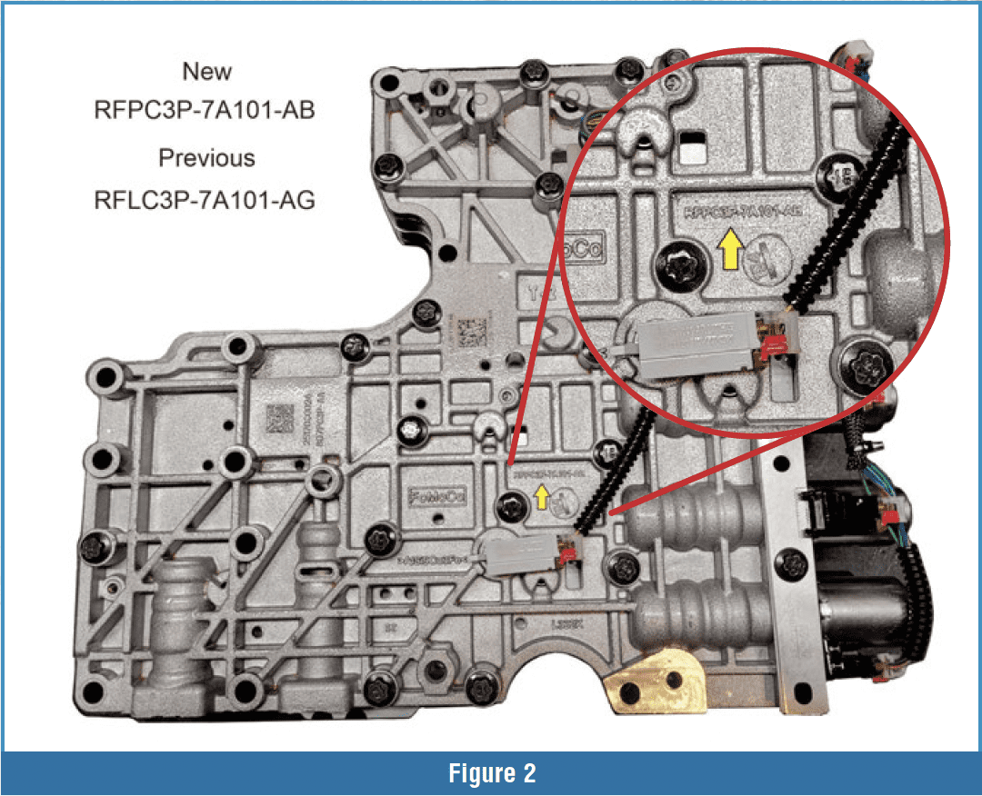
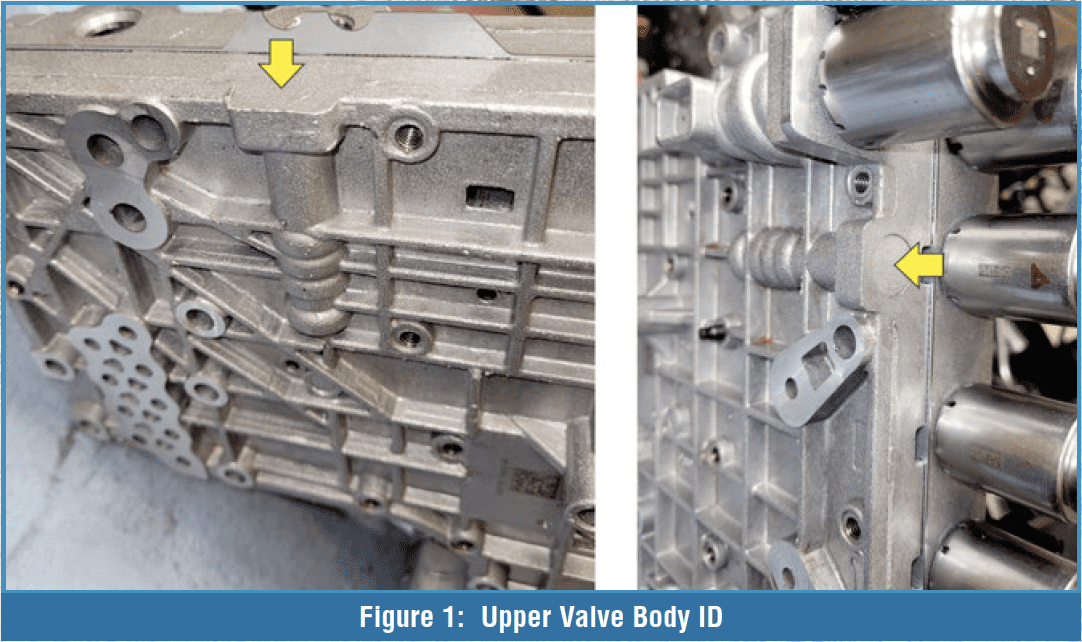 At first look, it is very similar to the previous design. But in a close-up view, notice that the upper valve body has cast over bores where the latch valves used to be (Figure 1). This is, of course, the easiest way to identify this valve body. Figure 2 also shows a new prefix for this valve body casting as PC3P.
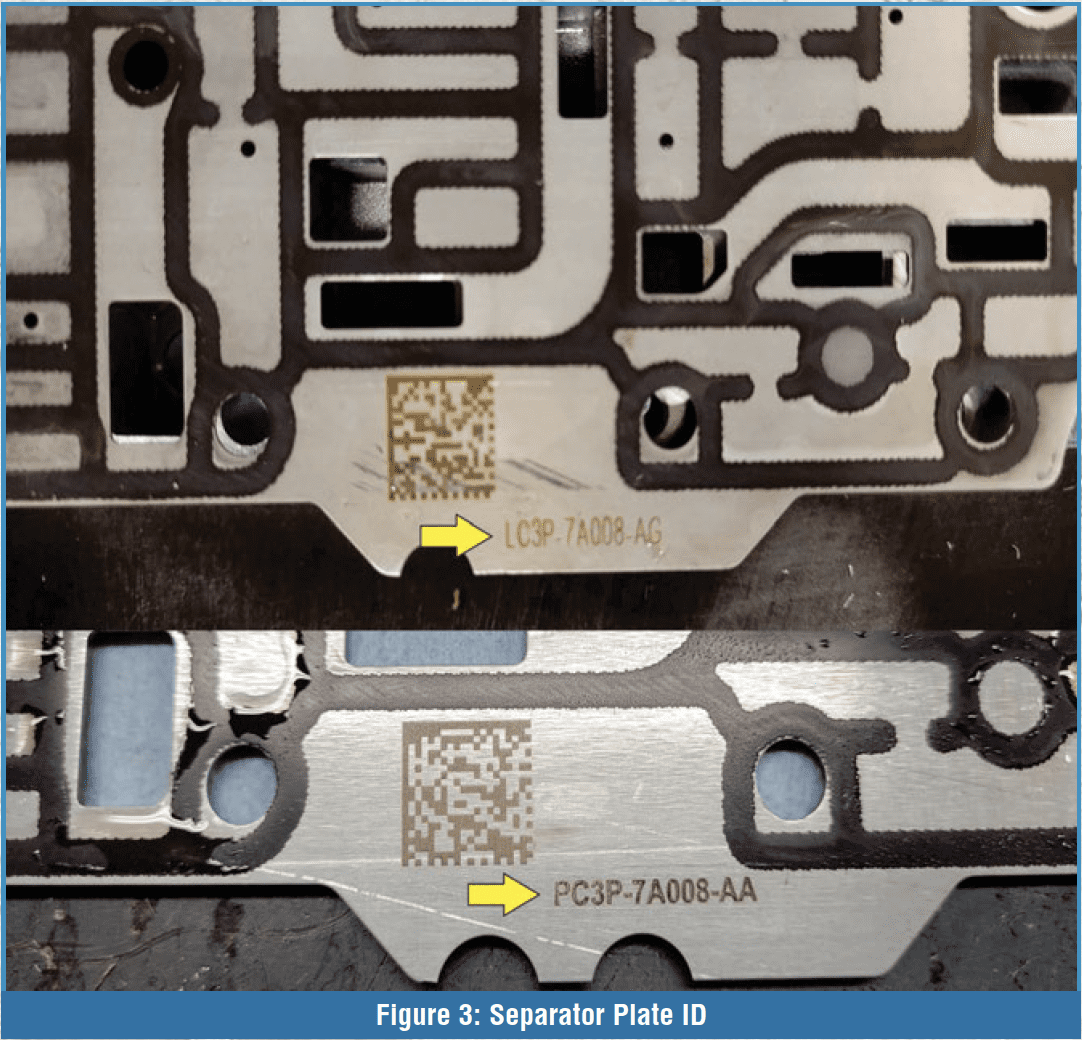
The separator plate has also changed. The ID, PC3P, has replaced the previous LC3P (Figure 3).

Disassembly of the valve body starts in Figure 4 with the lower section control valve locations as well as the locations for the relief check valves and damper assemblies.

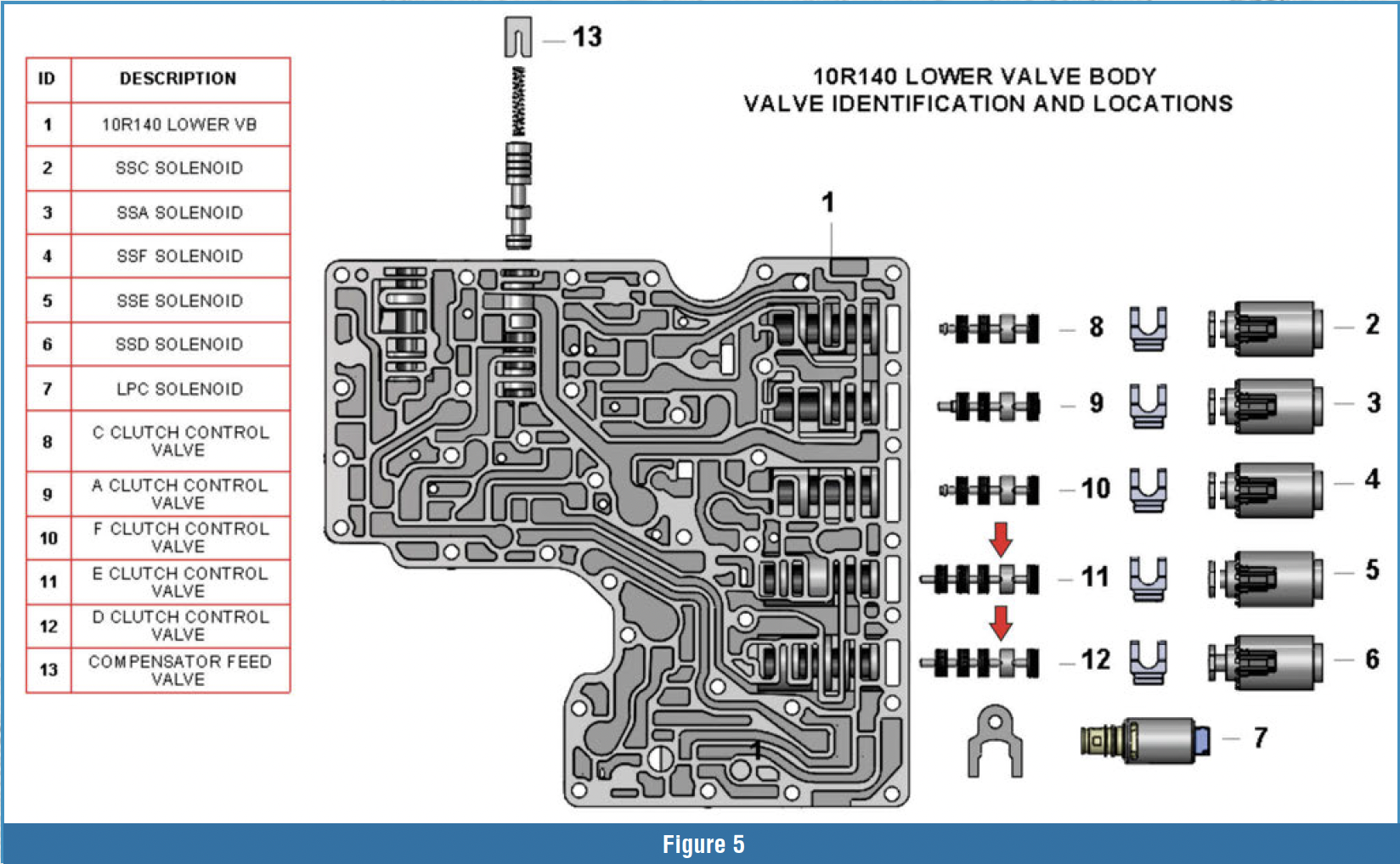
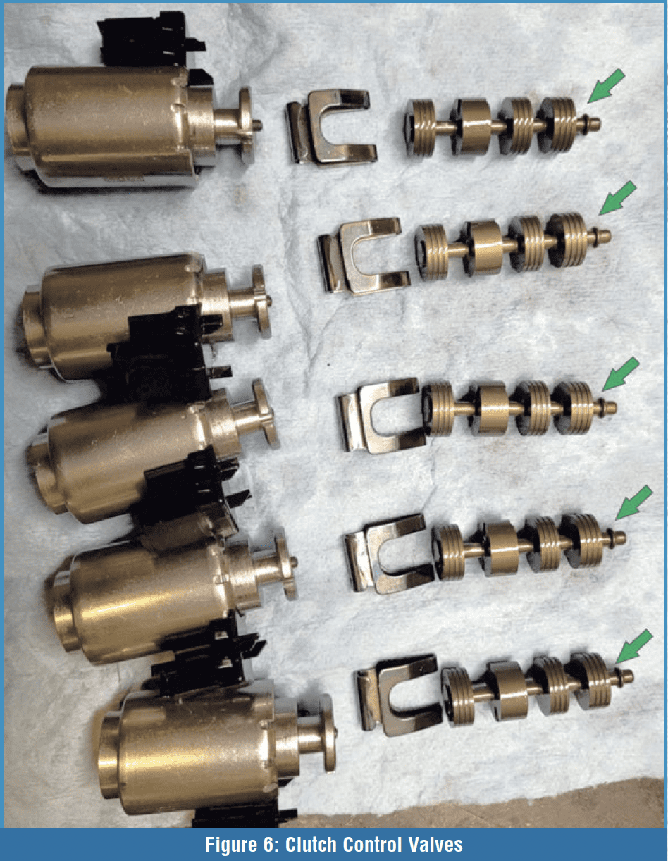
Notice that the clutch control valves have changed when compared to Figure 5, which shows the previous design. The clutch control valves for “E” and “D” have gone from a five-spool design to a four-spool design. Figure 6 shows a close-up of the clutch control valves on the ’23-later design, and notice that all of the control valves are the same and have the same ID on the stem of the valve.

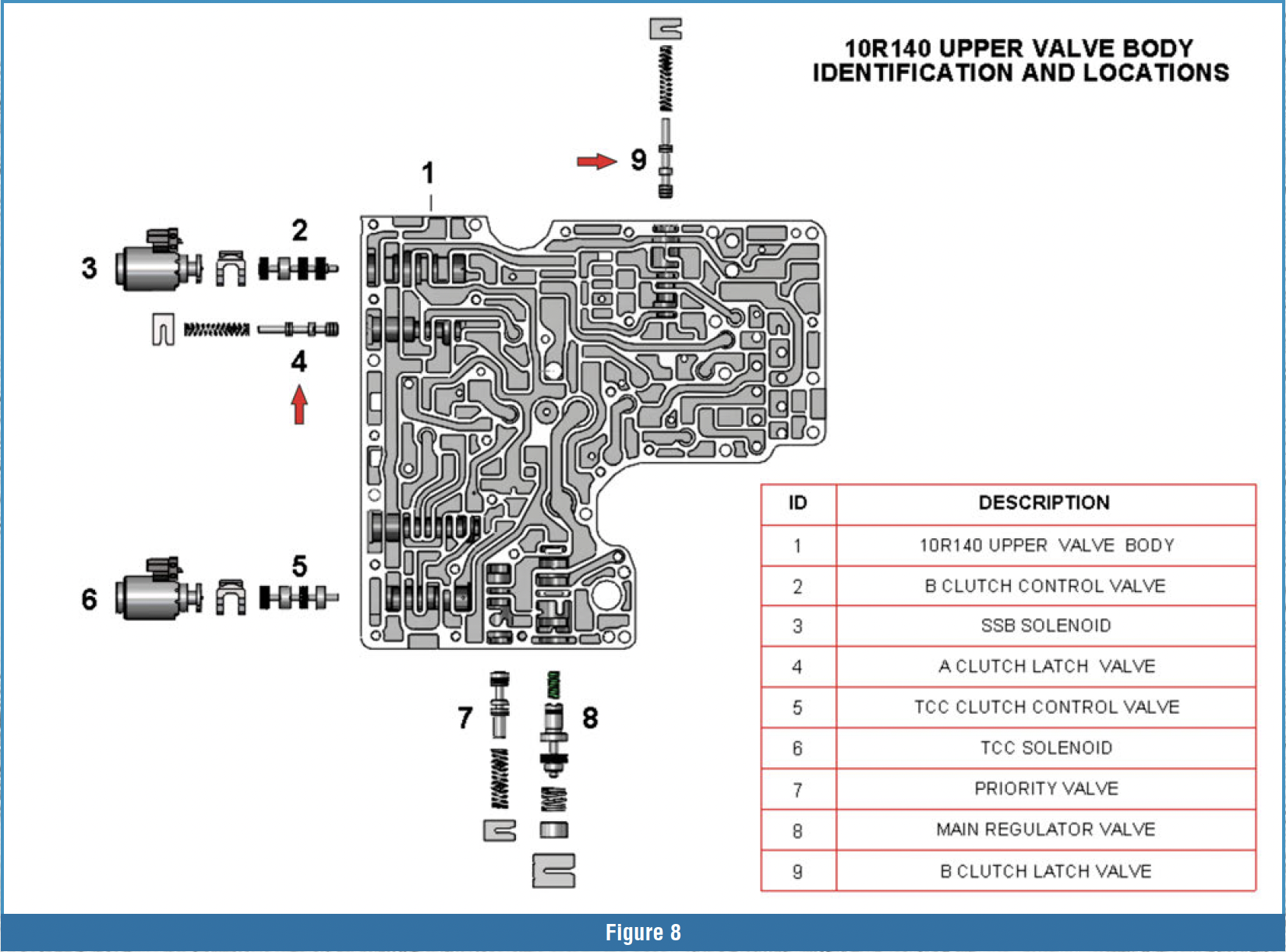
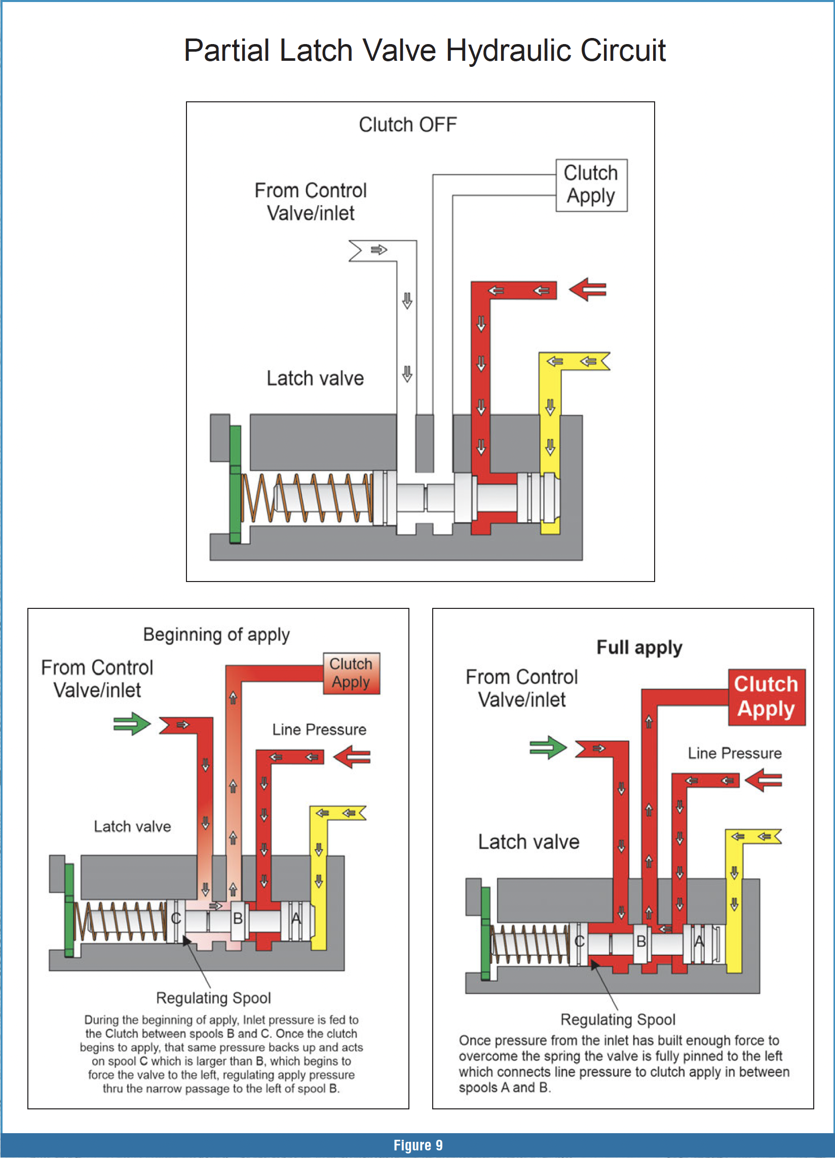

In this section of the valve body, the compensator feed valve had some small dimensional changes as well. Disassembly of the upper valve body starts in Figure 7. The casting for the “A” and “B” latch valve bores are not drilled as the valves have been eliminated. Figure 8 shows the previous-design valve body with the locations of the “A” and “B” latch valves. The latch valves are tied to the “A” and “B” control valves. These latch valves provide a full line pressure feed to the clutch when “A” or “B” clutch pressures are above 110–125 psi. Figure 9 shows a partial oil circuit of how the clutch control valves interact with the latch valves from when the clutch is released to the beginning of apply, then to full apply. The elimination of the latch valves is made possible by the change in the clutch control valves and TCM programming.
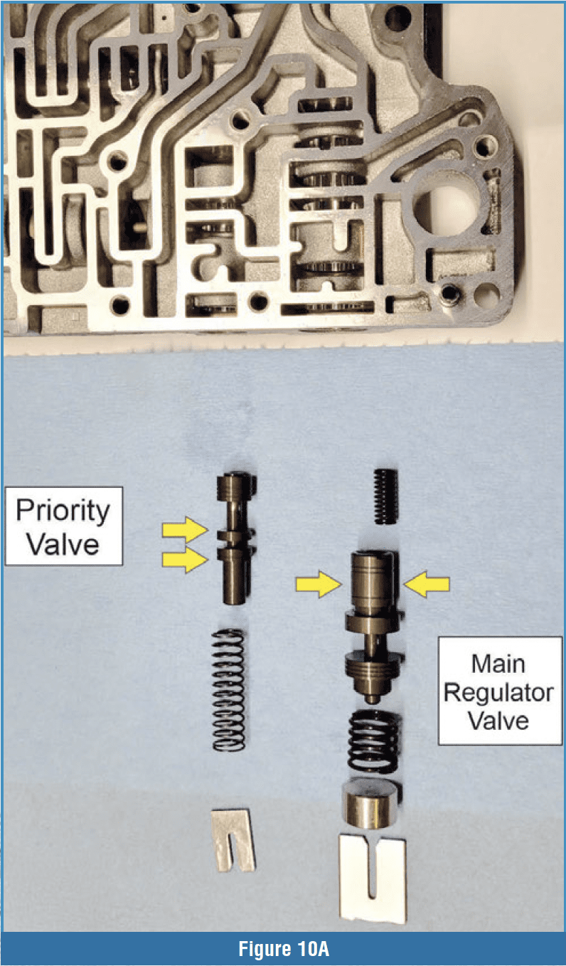
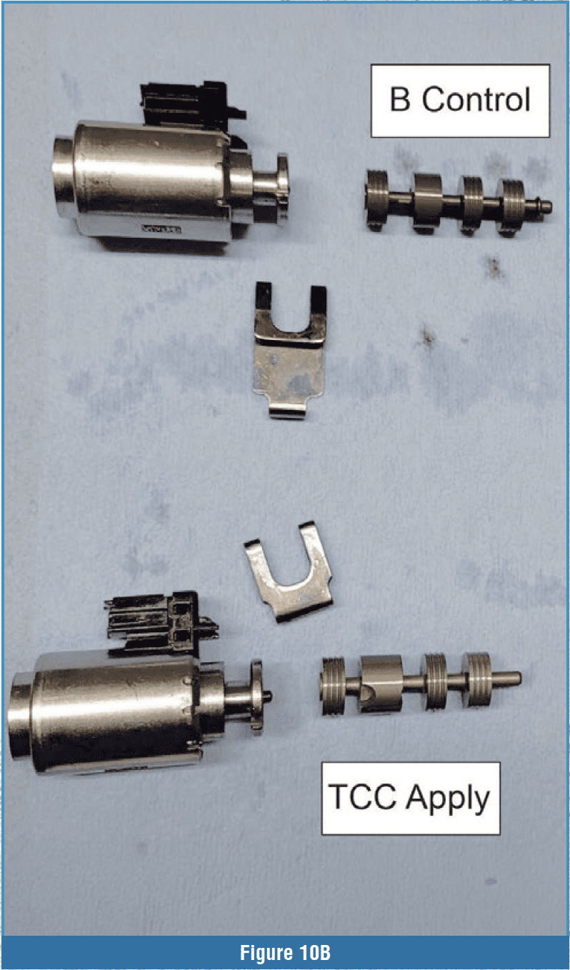
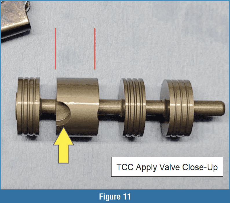
Upper valve body disassembly continued: The TC priority valve went to a split-spool design, and the pressure regulator valve changed dimensionally on the inboard spool (Figure 10A). Figure 10B shows the “B” clutch control valve and the TCC control valve. The TCC control valve had some dimensional changes to the second spool on the valve. This is where line pressure connects to the TCC apply circuit. Figure 11 shows a close-up view of this land. This spool has been elongated, and there are two cutouts where the connection to line pressure is. These cutouts help slow down and restrict the flow of the TCC clutch apply pressure.
Figure 12 shows a partial oil circuit of TCC apply of the previous design compared to the ’23-later design. This change may have come about because of firm TCC application complaints. The TC Clutch is applied under light acceleration right after 3rd Gear about 17–19 mph. TCC slip when fully on is typically 0–7 RPM, and the TCC slip will typically rise up to 40 RPM in between upshifts. The 10R140 uses a fourpath torque converter. There is TC charge, TC return, TCC apply and TCC balance (Figure 13).
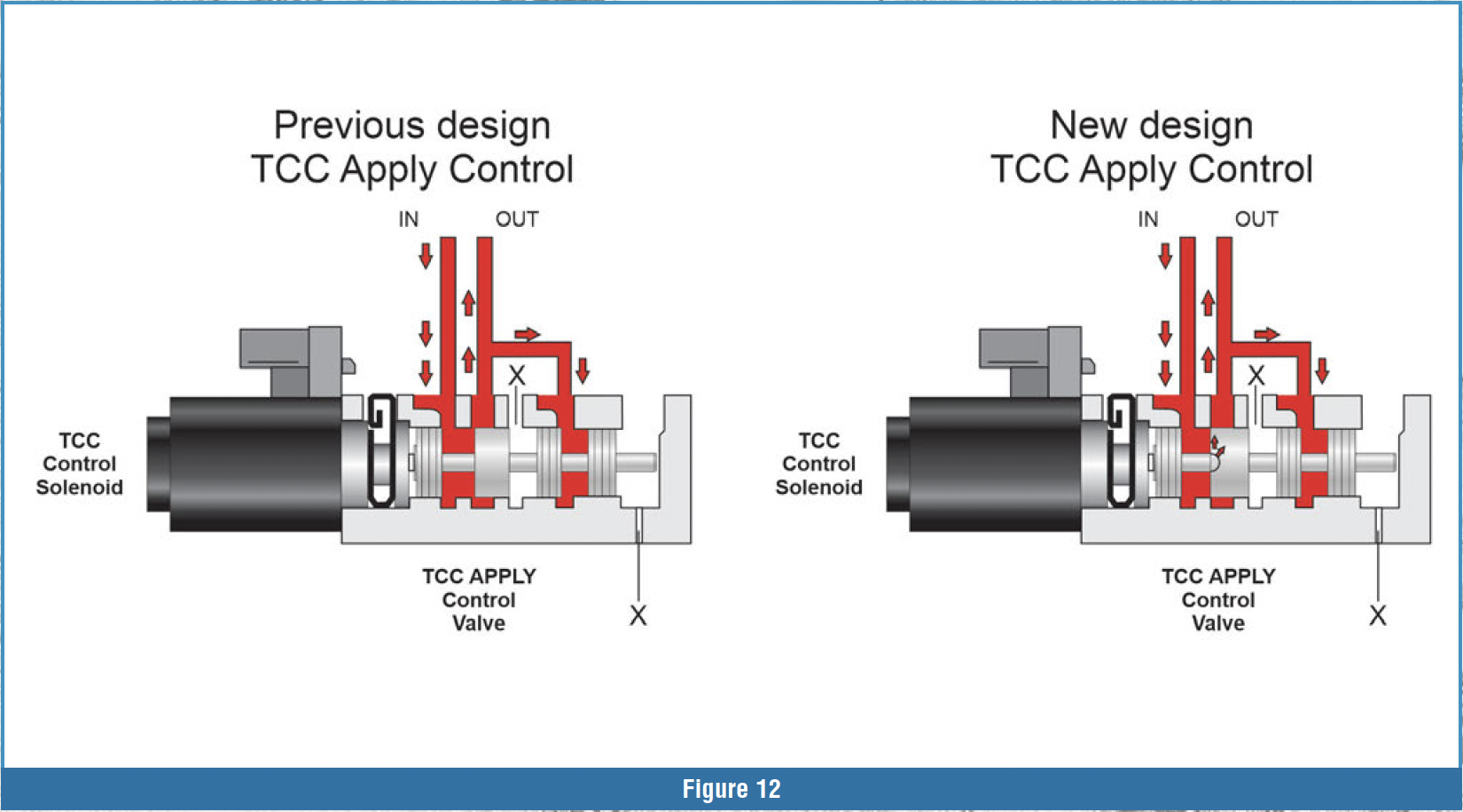

The TCC balance circuit is fed from a .020” orifice in the input shaft that is connected to the “D” clutch apply circuit. This balance feed is not a captive circuit. It provides a small amount of pressure, under 10 psi, to the opposite side of the TCC apply piston in the torque converter. This circuit helps provide a small amount of release pressure to help keep the piston off. The “D” clutch is on in all Forward gears except 5th and 9th Gears.
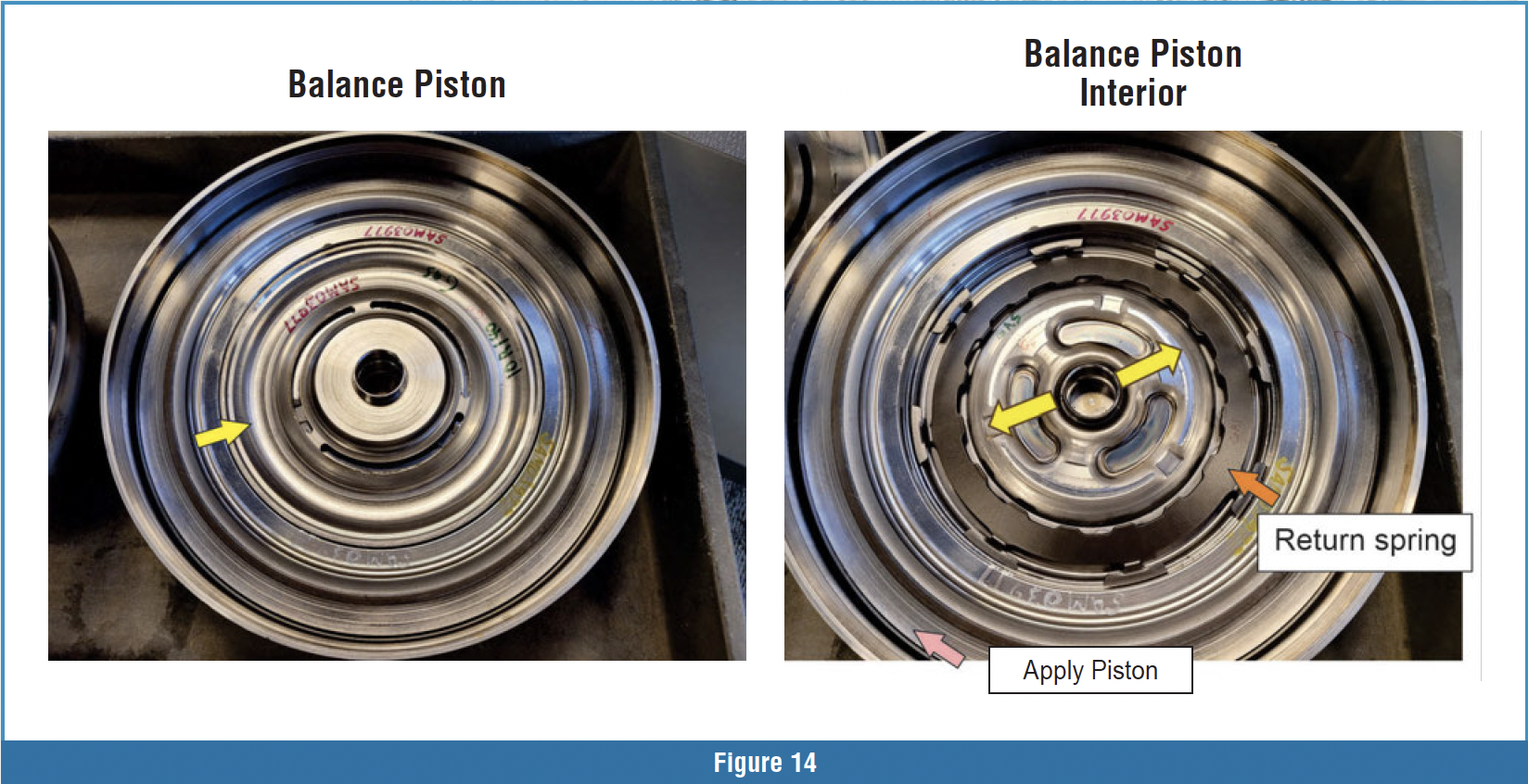
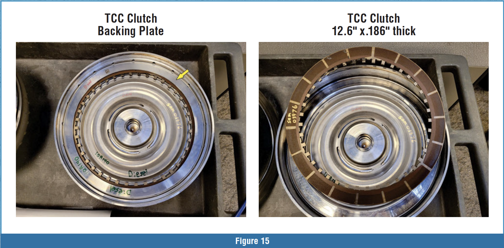
Figure 14 shows an internal view of the TCC balance piston and the return spring that the balance circuit works with to push the piston off. Figure 15 shows the torque converter clutch plate and the piston assembly as well as the backing plate over the clutch plate.
In closing, it is clear that Ford has looked at failure points on this transmission, as far as controls go, and dealt with them. A common failure on the previous-design latch valves was an issue with the stem of the latch valve slamming up against the notch in the retainer and turning the stem of the valve into a flat screwdriver tip. This has created valve overstroke and a problem with the valve sticking in the open part of the retainer. Ford made some big changes in the controls of this valve body to change the clutch control valves and electronics so they could eliminate the latch valves altogether. The change in the TCC apply valve was most likely due to harsh or firm TCC apply. The design change on the second spool of the valve could restrict the flow to the apply side of the clutch, which can help slow down the apply of the TCC clutch. Although it is sometimes hard to keep up with all the changes that come our way, it is nice to see that the OEMs are working on solutions.


