
Decades ago, when I started in this profession, electricity was one of those areas that most shops, technicians and even engineers, avoided when at all possible. Today’s vehicles are changing at a rate never before seen in the history of the automotive industry. With the advent of more speeds, more electronics, as well as most manufactures announcing that they have or will shortly unveil fully electric versions of their most common vehicles including pickups and SUVs, electricity is something that you can no longer avoid if you want to work in this industry.
Visiting independent repair shops and dealerships on an almost weekly basis, I see more and more repairs that require an understanding of electrical concepts as well as electrical diagnostic processes to correctly repair the vehicle. Without avail, I am asked much more about electrical issues than mechanical issues. During the seminars, we continually have discussions and questions regarding electrical issues at a much greater frequency as compared to mechanical issues.
The problem with electricity is that you cannot see it with your eyes or touch it with your hands like you can mechanical systems. This leads to apprehension on the part of the person repairing the concern. Most technicians are aware the electrical system typically consists of 6 parts:
- A power source (power side of the circuit).
- A ground or return path for the current to flow through back to the source or battery.
- A load (component) such as a light, solenoid, relay or motor.
- Wiring to connect the circuit/ components together.
- A switch or control device such as computer.
- Circuit protection such as fuses and circuit breakers.
Of any area that seems to give technicians diagnostic fits, it is the system grounds. A ground is the other half of the electrical circuit loop. A ground simply completes the path for the current/amperage to flow back to its starting point or source. In its simplest terms, it is the lowest voltage portion of the circuit (Using conventional theory electricity/current flowing from positive to negative).
Contrary to popular belief, the current/amperage (electron volume) is not consumed by the circuit or component but rather it does the work, as it is used to operate the component. Voltage (Electrical pressure) is used to force the current/amperage through the circuits and components. Voltage is the consumable in your electrical circuit and it should be consumed by the component and not the resistance of the wiring or its connections. If a connection issue exists, the voltage will be used to drive the current through the resistance in the poor connection leading to the voltage being consumed across the connection rather than the component. This will starve the component for current/amperage which will lead to issues with component operation such as a dim light, a solenoid or relay not fully energizing or an electrical motor turning slowly or not at all.
Many times, I ask the question regarding how the grounds look as they are typically the cause of many electrical issues. The response in lots of cases is, “they look great”. As I mentioned earlier, you cannot see electricity so the same is true then it comes to many connection issues. Yes, sometimes it is quite obvious that resistance is present as you can see corrosion on a connection, but most of the time the corrosion is not clearly visible but yet it may be the source of your issue.
You may wonder why the ground is the most common source of connection issues in a vehicle? The answer is typically because it is exposed to the elements, such as snow, ice, water, and road treatment chemicals such as salt and magnesium chloride. In addition, manufacturers are doing everything they can to control vehicle weight and cut costs in today’s vehicles. This includes making the wiring and terminals smaller and eliminating grounding washers. This has made wiring related issues much more difficult to deal with.
While visual inspection is still and important tool when it comes to wiring issues, testing the circuit and its grounds are more reliable methods to determine if an issue exists. No one method can be employed to test all types of vehicle grounds. Different technicians have different preferences when it comes to ground testing, these include:
- Ohm Meter Testing
- Load Testing
- Bypass Testing
- Voltage Drop Testing
 OHM METER TESTING
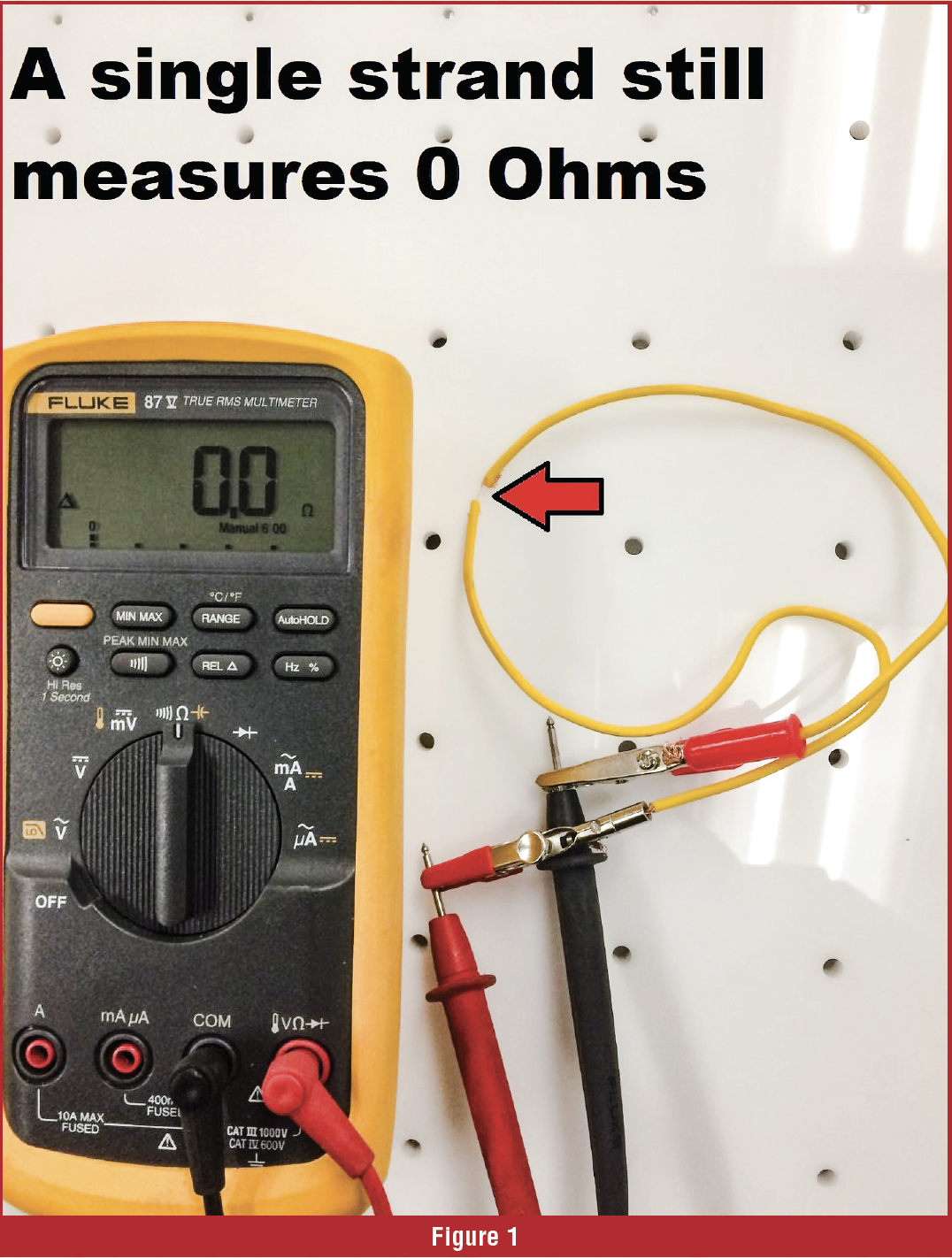
Your ohm meter acts as an ultra-sensitive voltmeter when it is placed in the ohms position. It supplies a tiny amount of current and voltage to one of the test leads. When hooked to a circuit or component, it measures the voltage consumed across the leads (voltage drop) and displays that as an ohm reading on the meter. Ohm meter testing is very limited in scope as it does not “Load” the circuit. This means that a conductor with only one strand of wire intact will register 0 ohms on the meter (Figure 1). If the damaged wiring is connected to the component it likely will not function as the amperage supplied to the component is now very low due to the damaged conductor. A lot of technicians get fooled by this which leads to frustration and a lot of good components being replaced as they assume based on their ohm meter test that the wiring and grounds are good.
To measure resistance, the circuit must be deenergized. This is one of the main disadvantages to using an ohm meter to test a ground as it is not in operation when you are testing it. So, in a nut shell, an ohm meter should NEVER be used to test an average-high current flow circuit or ground. So, when should an ohm meter be used to test a ground? Sensor grounds are probably the best example of when and ohm meter should be used. Sensors flow very little current so using and ohm meter is a good choice to find a bad sensor ground.
LOAD TESTING
A lot of technicians use the load test process to test a ground that they suspect may be bad. Most electrical diagnostic technicians have several different current flow value light bulbs in their tool box. Experience will tell you which bulb you should use. Connect the bulb to the ground that you suspect is faulty and attach the other end of the light to the battery + terminal. The lamp should fully illuminate, if it is dim or does not light at all the ground is bad. You need to be careful of a couple of things if you are going to load test a ground:
* Make sure the current flow capabilities of the light do not exceed the current flow capabilities of the circuit. This is why manufacturers typically do not advocate this type of testing.
* Do not use an LED type test light as a load test device. LED test lights are low current flow devices so it can fool you as the light may illuminate but the ground may not be able to carry enough current to make the circuit function.
Some specialized tools are also available to help you load test grounds. The “power probe” is a good example of this type of test tool.
BYPASS TESTING
Sometimes the ground may be very difficult to gain access too for testing purposes. Some technicians will choose to bypass the bad ground with jumper wires to see if the problem goes away. If it does, the ground or its wiring is at fault.
VOLTAGE DROP TESTING
Voltage drop testing is the preferred method for testing most grounds, with the typical exception being sensor grounds. Most manufacturers want grounds tested using this method as the circuit is in operation when the test is performed. As we discussed earlier, voltage is the consumable in and electrical circuit and the vast majority of the voltage should be consumed by the component and not the connections or circuit. Voltage drop testing allows you to see where the voltage is being consumed.
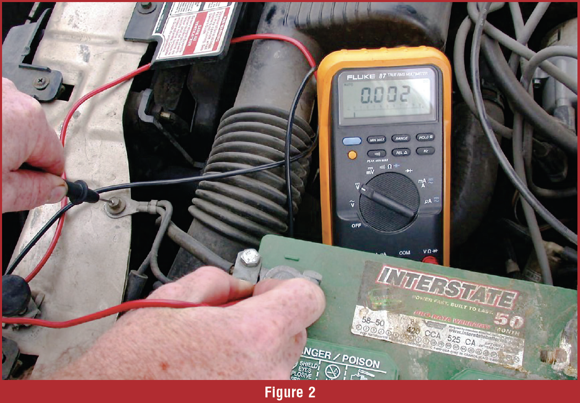
To voltage drop test a ground simply hook one of your volt meter leads to the suspect ground. Connect the other meter lead to the battery – terminal. “Energize” the circuit/ components and read the volt meter value (Figure 2). If excessive voltage drop is measured, resistance is present and it must be addressed. Some manufacturers provide specifications for the maximum voltage drop per connection or ground but a good general rule of thumb is .1-.2 volts per connection. The exception is when measuring a high current flow ground or connection like a starter motor which would of course be higher.

REPAIR
The folks that are probably the most experienced with ground issues is the US Navy. Connections are a huge concern on Navy vessels and they have spent a lot of time and money studying the issues. The MIL-STD-1310 was developed based on the studies of how connections are affected by torque, surface preparation and cleaning, the use of grounding washers and proper sealing of a ground connections. In a nut shell the standard recommends:
- The connection be cleaned chemically and physically to remove any corrosion.
- Ground bolt torque is critical as your ground integrity relies on physical contact for its connection.
- Grounding washers are recommended for many grounds as they assure good contact with the frame work the ground is attached to (Figure 3).
- Sealing and painting the ground after it is installed is critical to prevent corrosion from reoccurring as corrosion is due to the connection being exposed to oxygen. Without oxygen corrosion cannot develop.
So, the next time you get one of those pesky electrical issues to deal with, don’t lose any sleep over it, jump in and start testing. You will find that electrical testing is a little intimidating at first, but after you get the hang of it you will see that it is really not that bad. Until next time remember “there is a reason the windshield is bigger than the rear-view mirror, don’t look back, look forward”, the future will be exciting.


