In the first part of this scope series, published in the April 2026 issue of Gears, I introduced the idea that an inexpensive Pico 2204a could serve as a good introductory scope and that it can handle many of the automotive-based diagnostic tasks. It’s a great way to get started with scope-based diagnostics without a huge investment. The second article published in the October 2026 issue of Gears focused on using this inexpensive scope to check various input circuits. In this article, I’ll explain how to use the scope to check output circuits, such as injectors, solenoids, and coils. As figure 1 shows, an electronic control system contains input devices that are mostly low-current, low-voltage components that provide a processor with the necessary data to control output devices. The output components are typically higher-current electromagnetic devices that ultimately control vehicle operation.
 As a quick review, a digital storage oscilloscope (DSO) displays voltage over time, letting you check for signal dropouts, unwanted noise, and incorrect voltages, and with additional equipment, you can also measure current to help identify poor connections and faulty components. A multichannel scope also lets you compare signals to check for proper synchronization, like cam and crank sensor signal alignment.
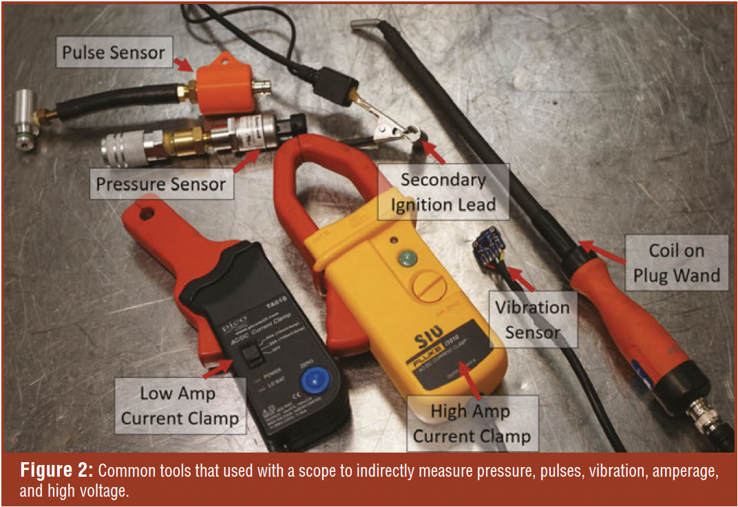
You can monitor anything that outputs a voltage with a scope. And just as the PCM monitors voltage to determine everything from temperature to pressure to position and RPM, various tools can convert these functions into voltage. That’s the function of an amp clamp, pressure transducer, speed sensor, vibration sensor, pulse sensor, and temperature sensor (Figure 2).
 TIPS FOR TESTING OUTPUTS WITH A DSO
Know what good looks like before testing – If possible, scope a good component before condemning a suspected bad component. For example, if you have misfire, check a coil and/or injector on a good cylinder before checking the suspected bad cylinder. Observe the pattern and how the signal reacts on a known good before condemning a part as bad, or you risk learning the hard way that you hooked up the scope incorrectly, or the pattern was actually normal.
When in doubt, use attenuation; most outputs, aside from lighting and heater elements, use electromagnetism. Review the outputs in figure 3; they all work on electromagnetic principles, and inductive voltage spikes often accompany electromagnetic devices. Inductive spikes occur when the changing magnetic field cuts across conductors and induces voltage back into the circuit (Lenz’s Law). This principle is how an ignition coil generates tens of thousands of volts to fire a spark plug. Keep in mind that when testing electromagnetically controlled outputs (relays, injectors, solenoids, actuators, motors, etc.), inductive spikes are possible.
To be safe, it’s a good idea to use attenuation to protect the scope from excessive voltage. With an attenuator installed, the signal will still be clean enough to evaluate, and if you notice there isn’t an inductive kick, you can always remove the attenuator if desired. It’s better to be cautious than to risk ruining a scope from excessive voltage. But to clear up a common misconception, you only need attenuators if the scope is exposed to higher-than-rated voltage. Capacitive or inductive leads, like secondary spark plug wire clamps or amp clamps, don’t require attenuation because the scope isn’t directly exposed to high voltage.
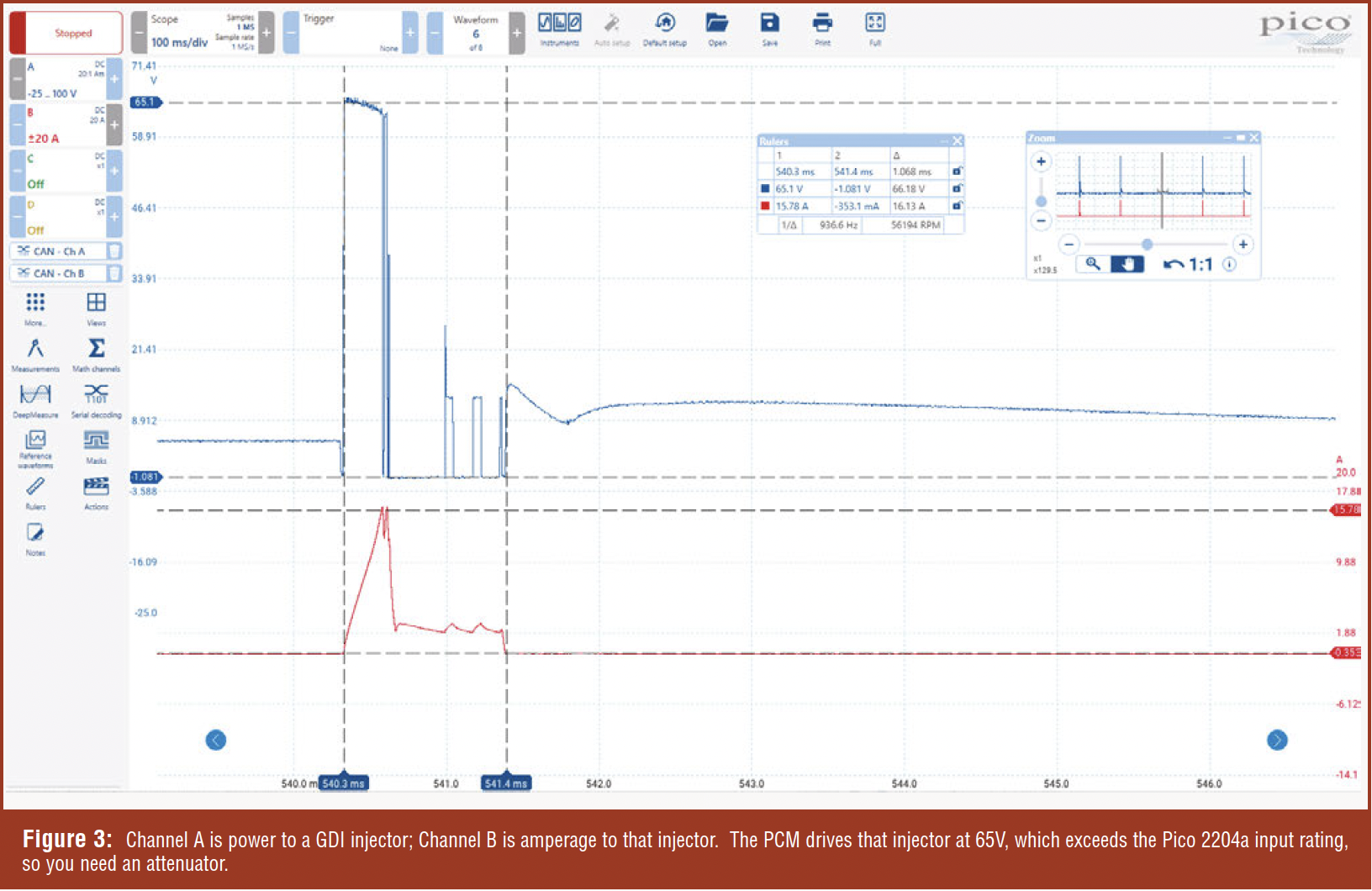
If you are following along in this article series with an actual Pico 2204a, you’ll notice the scope’s max input voltage is only 20 volts. The supplied lead set includes a 10x attenuator switch built into the lead, which reduces the voltage the scope sees by a factor of 10. Setting the 2204a probe to 10x lets you check circuits that could reach up to 200 volts, which is adequate for solenoids, actuators, relays, and injectors, but not high enough to check the primary of an ignition coil. If you find yourself needing to check the coil primary, you’ll want to purchase a 20x attenuator. Most modern vehicles, except some Stellantis vehicles, don’t allow primary voltage measurements at the coil because they use an ignitor circuit within the ignition coil. The PCM sends a low-voltage squarewave signal to a transistor within the ignition coil (typical of 3- and 4- wire coils). On those systems, you are limited to low-voltage power, ground, and signal measurements, secondary voltage measurements, and primary amperage measurements. For all those measurements, you won’t need an attenuator. Either way, many 2204a users buy a couple of 20x attenuators and new scope leads to expand the scope’s functionality. You can get these online at Amazon, Topdon, Rotkee, or aeswave.com, among others. Great accessories to accompany your scope include leads and attenuators, piercing probes, back-pin probes, ignition pickups, pressure transducers, and pulse sensors.
VALUE OF A SCOPE WHILE MEASURING OUTPUTS
Jerry Stewart has an excellent article evaluating current waveforms for injectors, solenoids, and coils in the August/September 2026 issue of Gears. Refer to that article for a more detailed waveform analysis. This article will help you “get started” using a scope to evaluate outputs and hopefully build confidence in scope-based diagnostics. Keep in mind that you can perform every measurement Jerry explained in his article with the inexpensive Pico 2204a, plus an inductive amp clamp.
MEASURING AN OUTPUT’S VOLTAGE/CURRENT
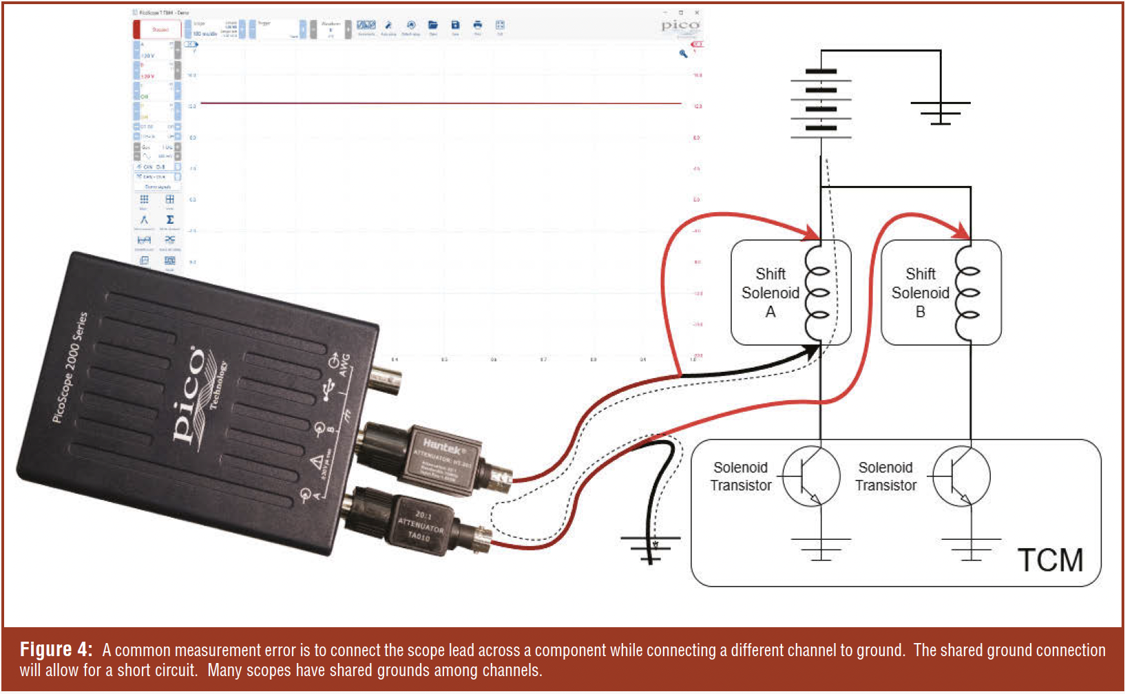
Direct measurements – A scope only measures voltage, so a direct measurement of an output would include checking for proper voltage, and if the circuit switches or pulsewidth modulates, you can ensure that the circuit is pulling to ground and building up to the source voltage as required. Remember from part one of this article series to make it a habit to connect the scope ground lead to battery ground. This matters when using multiple channels because both channels of the 2204a share a ground. Imagine connecting across a solenoid circuit where the ground will have 12 volts when commanded OFF, but having your other ground lead connected to a normal chassis or battery ground (Figure 4). With this misconfiguration, the solenoid will always have a ground path and try to energize, even when commanded off, since it can find a path to ground through the scope and scope leads.
 Indirect measurements allow a tool to convert a non-voltage measurement to a voltage, such as an inductive amp clamp. Since the scope only measures voltage, you cannot directly measure amperage by placing the scope in series with the circuit, as you can with a Digital Multimeter (DMM) (although a DMM also calculates amperage from voltage drop, unlike a DSO, you can pass current through the DMM). An inductive amp clamp lets the scope measure current because it converts the amp clamp’s current measurement into a voltage the scope can display. When you indicate to the scope that an amp clamp is in use, the Pico will change the scaling and units to display amperage.
Here’s a setting tip. If the Picoscope 7 T&M (for use with the 2204a) probe library doesn’t have your custom probe, download the automotive version of Picoscope from picoauto.com, allow it to open in demo mode, change the channels’ probe setting to reflect the automotive amp clamp (or any probe you need), run the scope for a moment, then save the file. 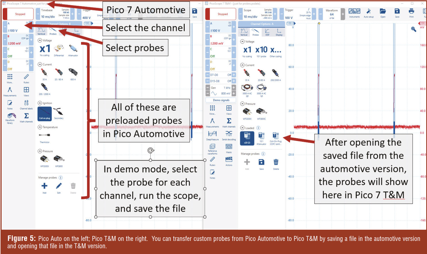 Now open that saved file in the Picoscope T&M program, and you’ll see the new probe in the “probes” list and in the “loaded” section (Figure 5). You can manually set up the amp clamp or any custom probe, but if the probe already exists in the automotive version of Pico, you can simply transfer the probe and its settings to the T&M version. Why not simply use the automotive version of Pico? Because the 2204a isn’t considered an automotive scope; therefore, the automotive version of Pico doesn’t recognize it.
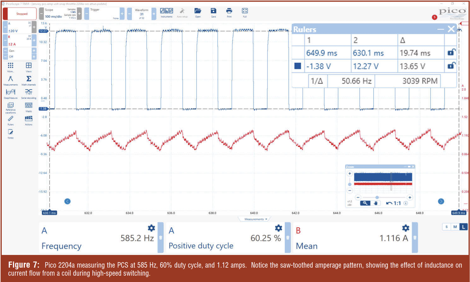
With respect to electromagnetic outputs, voltage pushes electrons through a circuit, but it’s the amperage that does the electromagnetic work. Current flow creates a magnetic field, and any output relying on magnetism needs proper current flow to operate properly. Since the computer controls current by pulse-width modulating voltage, a scope can do a great job ensuring the circuit is operating correctly. 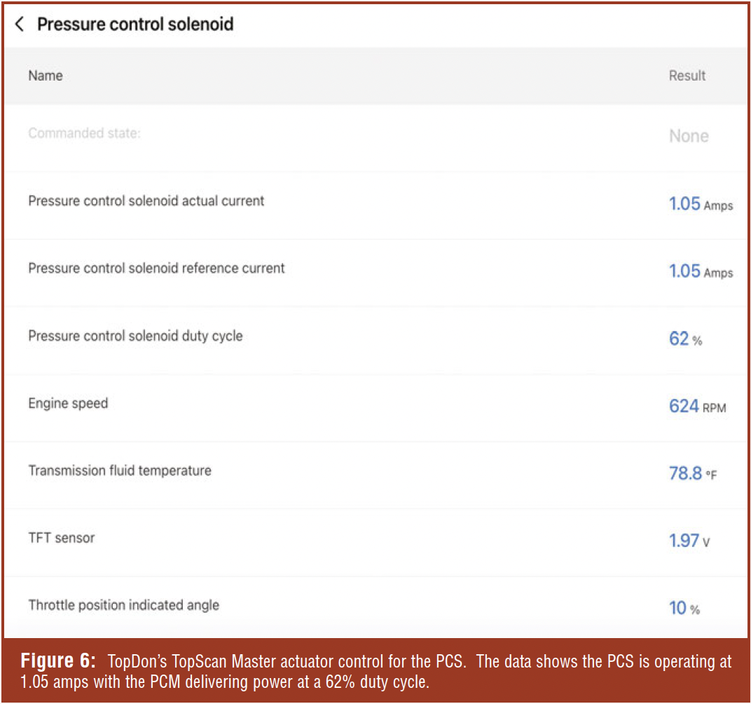 For example, the Pressure Control Solenoid (PCS) circuit shown in Figures 6 and 7 operates at 585 Hz (cycles per second), and the computer provides power 60-62% of the time and ground 38-40% of the time. The PCM changes the duty cycle to achieve the proper current flow, which the scan tool reports as 1.05 amps. In this case, the scope shows the PCS operating at about 1.12 amps, which is close to the commanded amperage. The computer is programmed to know that at 1.05 amps, the transmission should generate about 70 psi. If the PCM wants more pressure, it will modulate the solenoid OFF more, since this solenoid defaults to high line pressure with no power (inversely proportional solenoid). Comparing this scope amperage data to the scan tool-indicated amperage ensures the PCM is controlling the solenoid properly.
USE VOLTAGE AND AMPERAGE TO DETERMINE RESISTANCE
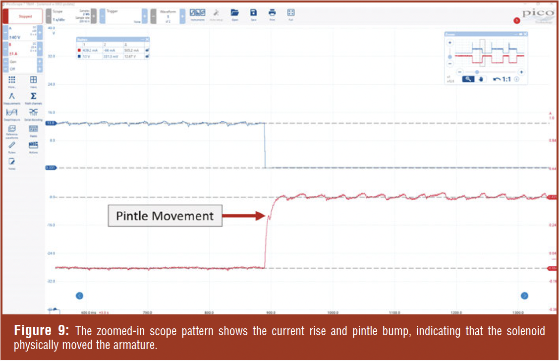
Circuit resistance can be calculated by using voltage and current measurements. This is a much better method than simply measuring with an ohmmeter, especially on a circuit that pulls a decent amount of amperage. Since the circuit is connected and attempting to work, and likely passing more current than the ohmmeter provides, this makes it a more comprehensive resistance test. Figure 8 shows the results from monitoring a common shift solenoid circuit. With channel A connected to the ground side of the solenoid, and channel B measuring current flow, the scope pattern shows source voltage when off (13v), voltage pulled to ground when energized (0.3v), and an amperage of 0.5 amps. 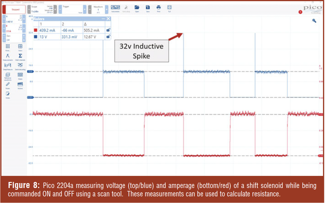 With the supply circuit providing 12.7 volts and 0.5 amps, dividing the voltage by the amperage gives a resistance of 25 ohms. These solenoids should be between 20-40 ohms, so the solenoid is within spec. This process checks the solenoid, circuit, connections, power, grounds, and the PCM’s transistor for a comprehensive electrical analysis. You can also run these tests under the same conditions as the transmission failure, such as when hot or in a particular gear. Zooming in on this pattern (Figure 9) shows the solenoid plunger stroking by observing the “pintle bump” signature described in Jerry’s waveform analysis article. It’s worth noting that, as described, these resistance calculations work best on non-PWM electromagnetic components.
 You couldn’t reliably perform the same measurement on the PCS circuit discussed above because the solenoid’s inductance affects current flow as it switches on and off at a high frequency.
CONCLUSION
Getting started with scopes can be daunting. There’s a lot to learn about the process, not to mention deciphering the results. If you are “getting started with scopes,” this article series and the Pico 2204a will help you navigate the learning curve and provide insight into circuit operation that a scan tool or DMM won’t. Go back to image one and look at all of those output components. You can successfully evaluate those components using the scope by monitoring voltages and amperage and get a good idea if they are functioning properly. In the next article, let’s continue this journey by exploring custom probes and diagnostic tests that will help you diagnose those tough-to-solve issues.