Diagnosing a transmission problem requires an understanding of more than its mechanical operation. Today’s transmissions are also programmed to respond electrically to the inputs and information received by the ECM/PCM. When those mechanical and electronic systems interact, a problem in one area can easily be mistaken for a problem in another.
We received a call from a local shop that had rebuilt a U151 transmission in a 2005 Toyota Sienna AWD. After the rebuild, the 2-3 shift was harsh and, at times, felt like it was binding with no DTCs.
The shop had already tried several solutions. Since there were no DTCs, they reset the transmission adaptations, installed three different valve bodies, replaced the TISS and OSS sensors, and even replaced the ECM. Nothing corrected the problem.
We asked the shop to send us a scanner movie showing the relevant PIDs so we could see exactly what the transmission was doing during the shift. Unfortunately, they didn’t have a scanner capable of recording and sending the information we needed, so they sent us the vehicle instead.
Once we had the Sienna in the shop, we connected our scanner, which had the latest software available. However, we discovered that it did not provide access to the TISS and OSS PIDs. Since those signals were important to our diagnosis, we went directly to the ECM to obtain the TISS and OSS readings.
Why were we interested in these particular signals? Because of the role they play in transmission adaptation, particularly when it comes to the quality and timing of the 2-3 shift on this transmission. A compromised signal would cause a poor shift.
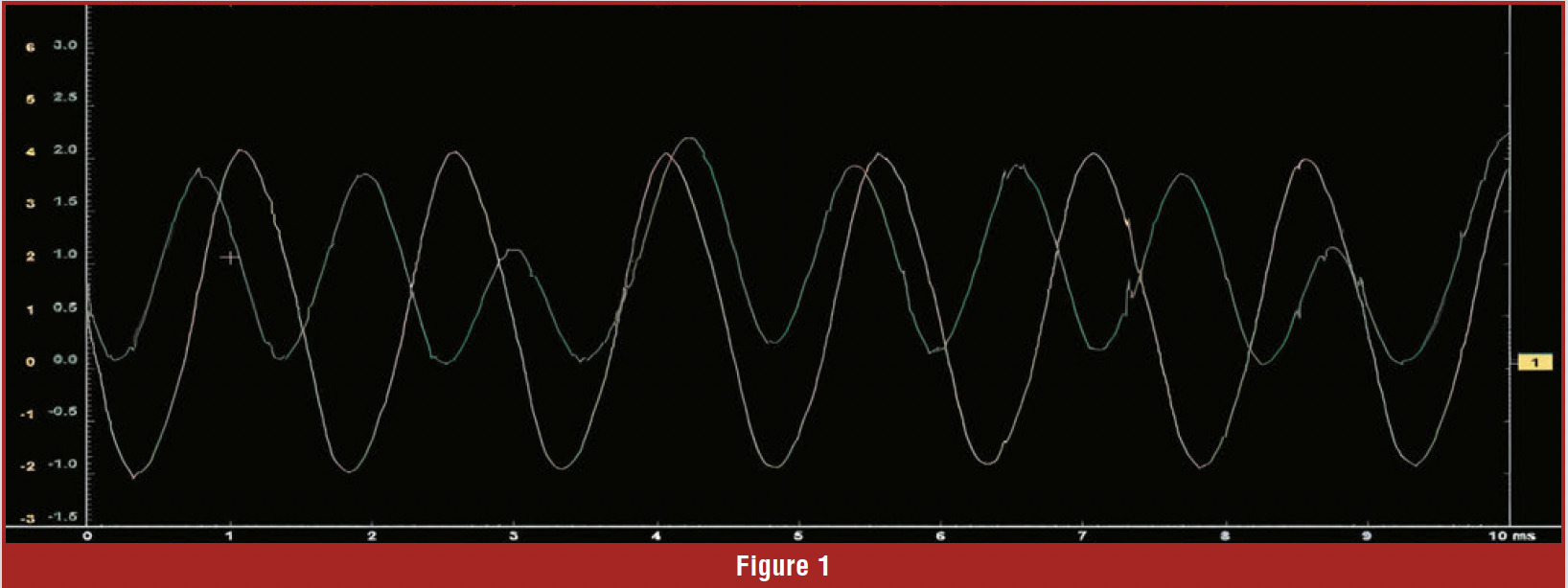
We put the TISS and OSS signals on the scope, with TISS displayed in yellow and OSS in green. After reviewing the waveform, the problem became clear (Figure 1). It was obvious that the OSS signal was distorted. Notice that there are pulses that are lower in amplitude than most of the others.
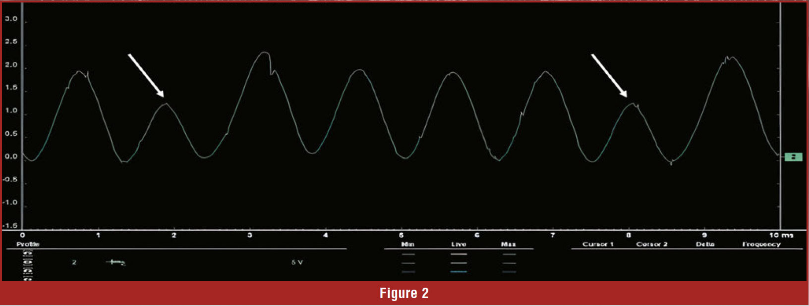
In Figure 2, we turned off the TISS trace from Channel 1 to give us a clearer view of the OSS signal. Notice that at least two damaged teeth are visible in the waveform. The amplitude of voltage reading on two of the pulses is noticeably different from the other signals, indicating that the gear was not producing a consistent signal as it rotated.
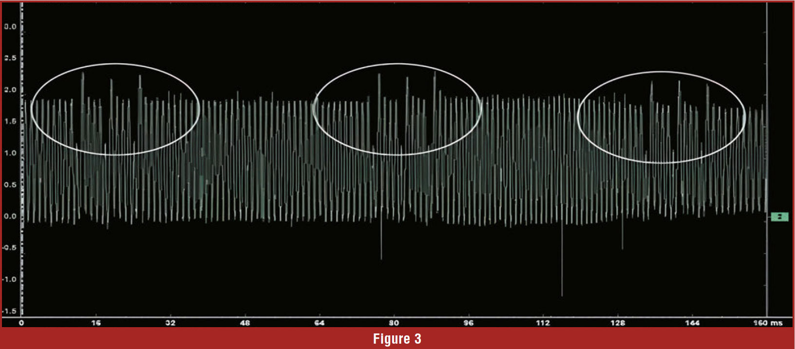
In Figure 3, we zoomed out 16 times. This allowed us to see the complete pattern and identify three broken teeth occurring during every revolution of the counter gear.
With this information in hand, we called the shop and told them to remove the transmission and replace the counter gear. The gear had three broken teeth.
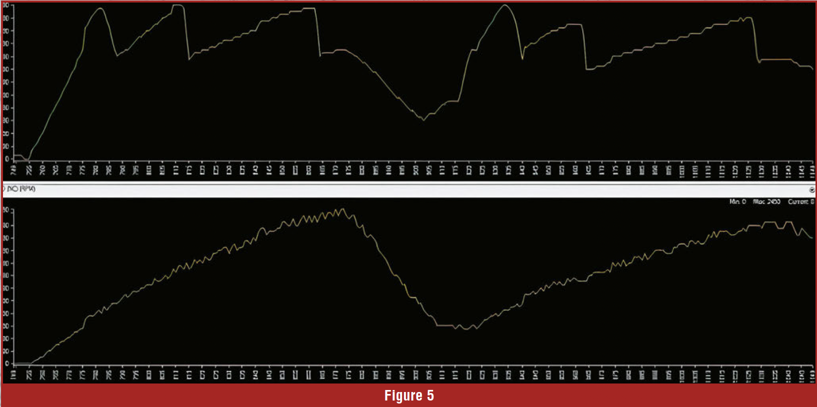
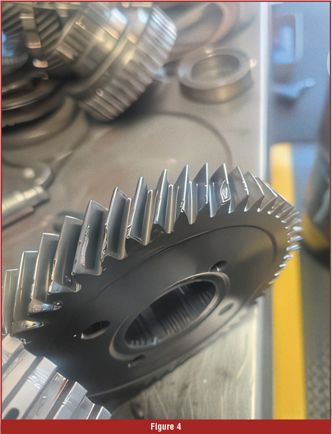 Figure 4 shows the actual broken teeth on the counter gear, while Figure 5 shows what the OSS PID waveform looks like with a single broken tooth in high resolution.
Once the counter gear was replaced, the transmission was reassembled and returned to service. The transmission then operated flawlessly.
The lesson is simple: a transmission- related symptom doesn’t always mean the problem is inside the valve body, sensors, or control module. Understanding how the mechanical components generate the electronic signals used for transmission control can lead you directly to the real problem.
So, the next time you’re chasing a hard shift, don’t overlook the signals behind the shift strategy. Don’t let a couple of broken teeth ruin your lunch.