There are many things that can cause torque converter clutch (TCC) cycling on Dodge diesels, from poor grounds to a failed fuel pump or a plugged fuel filter.
Disconnecting the battery will almost always cure the problem for a couple months. The reason disconnecting the battery seems to correct the problem is because it resets the PCM’s adaptive memory. But after the vehicle is on the road for a while, the computer readapts and the problem returns.
That’s why simply cleaning the battery cables isn’t always the best course of action, since you can’t be sure if it cured the condition permanently.
Here are some preliminary checks to help determine the cause of TCC cycling on the Dodge Cummins diesel:
- Both batteries usually have a pass-through connector between the negative (–) battery post and the chassis ground. This connector often corrodes, creating a poor ground path. Always disconnect the connector and inspect the contacts — if they’re corroded, you can eliminate the connector by cutting the wires and soldering them together. Don’t use a butt connector; it’ll just corrode again.
- Beware of old, weak batteries or mismatched batteries. Just because the engine starts doesn’t mean both batteries are good. Load test each battery individually once you’ve checked all other possibilities. Never disconnect the batteries before performing a thorough diagnosis. And never replace just one battery; always replace them in pairs.
- A poor connection at the output speed sensor (OSS) is very common. It’ll cause an intermittent signal dropout, which causes the torque converter clutch to unlock. The wires break inside the insulation, usually within 6” of the OSS connector. Sometimes you’ll see bare wires right where they meet the connector.
- Monitor the OSS signal on a scan tool while an assistant runs the vehicle up on a lift.
- Pull on the OSS wires while the rear wheels are spinning and see if you can make the signal drop out.
- If the wires are broken, replacement connectors are available.
- Anything from a poor connection at the park/neutral switch to an intermittent short at the transfer pump can cause TCC cycling or 3-4 hunting on a 47RE transmission. A faulty crankshaft position sensor is another possibility. If you see engine RPM in the live scan data go over 5000 on a diesel, it’s a dead giveaway.Always take the vehicle on a long test drive while recording the data from the transmission inputs. Try to limit the data you’re recording by eliminating the PIDS that won’t be useful. The PIDS you want to monitor are:
- Brake switch
- Park/Neutral (P/N) switch
- Engine RPM
- Transmission Temperature
- Output Shaft Speed Sensor (OSS)
- Vehicle Speed Sensor (VSS)
- Throttle Position Sensor (TPS) or Accelerator Pedal Position Sensor (APPS)
You’re most likely to reproduce the symptoms at light acceleration, from 40-50 MPH (64-80 kM/H). Accelerate as lightly as you can at 40 MPH (64 kM/H) and you’ll feel the torque converter clutch engage somewhere between 40-45 MPH (64-72 kM/H). If you hold the accelerator steady at about 5%, it’ll usually cycle the TCC a few times before you reach 50 MPH (80 kM/H).
Try to capture a couple of failure events in your data recording and analyze it in Shop-Stream.
If the engine lacks power, be sure to repair any engine performance issues first. Failed injection pumps and plugged fuel filters are common.
If everything else checks out, it’s time to get into some serious diagnostics that are actually fairly simple.
If you don’t have a lab scope and you’re diagnosing transmission problems on a daily basis, think about getting one. You’re going to need a lab scope to diagnose today’s vehicles. If you’re just trying to figure out what’s wrong with this vehicle, try borrowing a lab scope or pay a professional to check the TPS/APPS signal for noise.
Test for Noise in the TPS/APPS Signal
- Locate the Powertrain Control Module (PCM) under the hood on the passenger side firewall. You can pull straight up on the air cleaner housing to disconnect it from the body and move it to the side for easier access; no tools required.
- Identify wiring connector C1. It’s on the far right of the PCM (closest to driver) and it’s black (figure 3).
- Find the orange/black wire that connects to pin 23 in the C1 connector. If you take the rear cover off of the connector it’s easier to ID the wire, but there’s usually only one orange/black wire to the C1 connector, so it should be easy to locate.
- Strip some insulation off the orange/black wire carefully with a single-edged razor blade; be careful not to cut the wire strands. You can also use a wire piercing test tool if you have one. Just make sure you’re at least 6” away from the PCM connector; you want to leave enough wire in case further repairs or splices are necessary.
- Connect a lab scope:
- Positive lead (+) to the orange/black wire, ground lead (–) to the ground cable on the battery post.
- Monitor DC voltage on the 2-volt scale.
The scope settings aren’t fussy but a simple voltmeter won’t work. You must have a lab scope or graphing meter with a very fast refresh rate. The Snap-on Vantage is probably the most popular tool. The Snap-on Modis and other high end Snap-on scan tools also have the Vantage integrated.
- Key on, engine off.

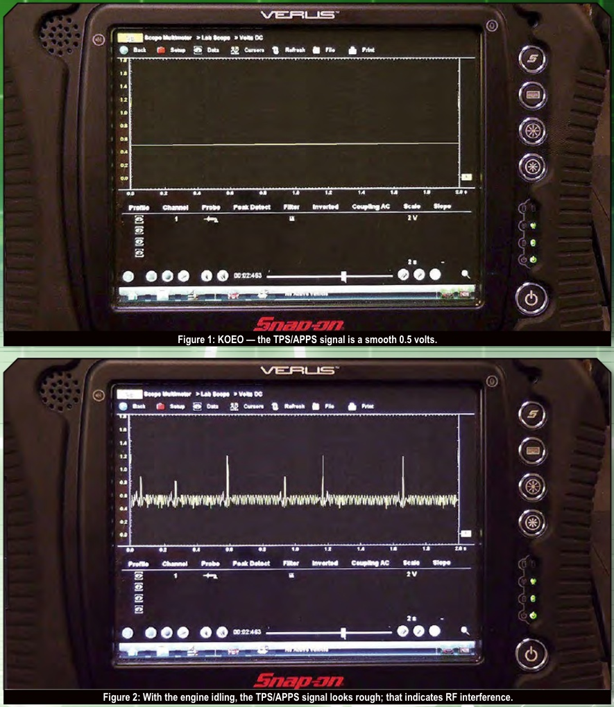
- Monitor the TPS/APPS voltage on the scope (figure 1). You should see a steady 1/2 volt. The line across the display should be straight, without any peaks or dropouts. Just a smooth signal around 0.5 volts.
IMPORTANT: The signal should be roughly 0.5 volts; it may be as low as 0.44 volts and still function just fine. This may indicate poor grounds. - Start the engine and let it idle. The TPS/APPS signal on the scope should still be relatively straight at roughly 0.5 volts.

If the TPS/APPS signal looks fuzzy with the engine idling (figure 2), but it’s nice and smooth with the key on, engine off, you have RF interference. You can correct this by installing a noise filter on the orange/black TPS/APPS signal wire right at the PCM. And you’ve already done half the work by stripping the insulation.
Installing the Noise Filter
Here’s how to install a noise filter on the TPS/APPS signal circuit (figure 3):
- Move the air cleaner housing out of your way as described earlier.
- Connect the positive (+) lead of the noise filter to the orange/black wire. Solder the connection and wrap with electrical tape.
An even better method is to:- Cut the wire.
- Slide some heat shrink tubing over one end.
- Twist the three ends together.
- Solder the connection.
- Apply the heat shrink with a heat gun.
If you twist them right, you should end up with one wire coming out one end of the heat shrink heading to the PCM, and two wires coming out the other end.
- Route the noise filter wiring against the top of the fender, under the air cleaner, and along the vehicle wiring harness.
- Connect the negative lead of the noise filter to the negative (–) battery terminal.
- Secure the noise filter with tie straps. It can be a really clean job if you hide the filter under the air cleaner assembly.
- Drive the vehicle and confirm the repair.
Tod Chretien is a diagnostician at Ralph’s Transmissions in Modesto California and president of the Transmission Rebuilder’s Network Worldwide (TRNW). Noise filters are available at the TRNW online store at www.trnw.net.