
The ZF 9HP48, also known as the 948TE for FCA (Fiat/ Chrysler Automobiles) vehicles, is a nine-speed transmission found in various Honda/Acura models, many FCA models, and a couple Land Rover models. For FCA alone, there are over 3 million of these transmissions found in the Jeep Cherokee, Renegade, Compass, the Chrysler 200, Pacifica, the Ram Promaster City, and the Fiat 500x.
When first released in FCA vehicles, the 9HP48 had numerous issues regarding shift quality, namely harsh upshifts and downshifts, delayed gear engagements, gear ratio error DTCs, stuck in-gear DTCs, and various other DTCs. Many of these issues were resolved through TCM programming, so when diagnosing this transmission, it is important to review TSBs and check for any outstanding recalls. When reviewing the TSBs from FCA, you will see that for every model and every year there is a TSB informing the technician to perform an update to the TCM. As can be expected, there were plenty of growing pains that accompanied this transmission.
History does repeat itself and this transmission is reminiscent of the 41TE when it was first released back in 1989 and then through the first half of the 90’s. Those early units kept dealers busy because they rarely made it out of warranty. So, what saved the 41TE? One major improvement was the software, along with enhancements in the computer hardware. The same basic 41TEs that couldn’t make 30,000 miles back in 1990 are still being produced in 2019 (Dodge Journey), but they’re rarely seen in transmission shops, because their reliability has improved greatly. Many of the improvements made to the 41TE were through software updates and, along those same lines, through using a computer that could be reflashed.


When reviewing the TSBs for the FCA ZF 9HP48, you’ll notice there are many software updates specifically for the 2014-2016 model years, and these updates cover a wide variety of issues, and now the later model units still have reflashes available, but they cover far less issues. Over time, the software is improving to the point where this transmission is becoming smoother and more reliable. As a side note, ZF provides basic software for the manufacturers using the 9HP48, but it’s up to the manufacturers to write software to control their specific shifting characteristics. This may be one reason why Honda/Acura hasn’t released software updates anywhere close to the same rate as FCA. This article is going to dive into the construction and operation of the 9HP48 and highlight some rebuilding particulars.
CONSTRUCTION
The 9HP48 has four multiple disc clutch assemblies and two dog clutch assemblies. The gearset is divided into three sections; a front, middle and rear gearset. The block diagram in figure 1 shows how the gearset is constructed. Note that items that are the same color are connected to each other. Compare the block diagram to the complete gearset in figure 2 to get a reference of the gears, drums and shafts.
COMMON CONNECTIONS
The output is always from the front carrier. The front internal gear is also connected to the middle carrier. The middle internal gear is connected to the rear carrier. The front and middle sun gear are one and the same. The rear gearset is unique in that there are two carrier assemblies and the large sun gear also acts as a small internal gear. This transmission is described as having four planetary gearsets, but I like to think of it as having three gearsets, since the rear gearset contains a small sun, a small carrier, and combination small internal/large sun gear, a large carrier and a large internal gear (figure 3).
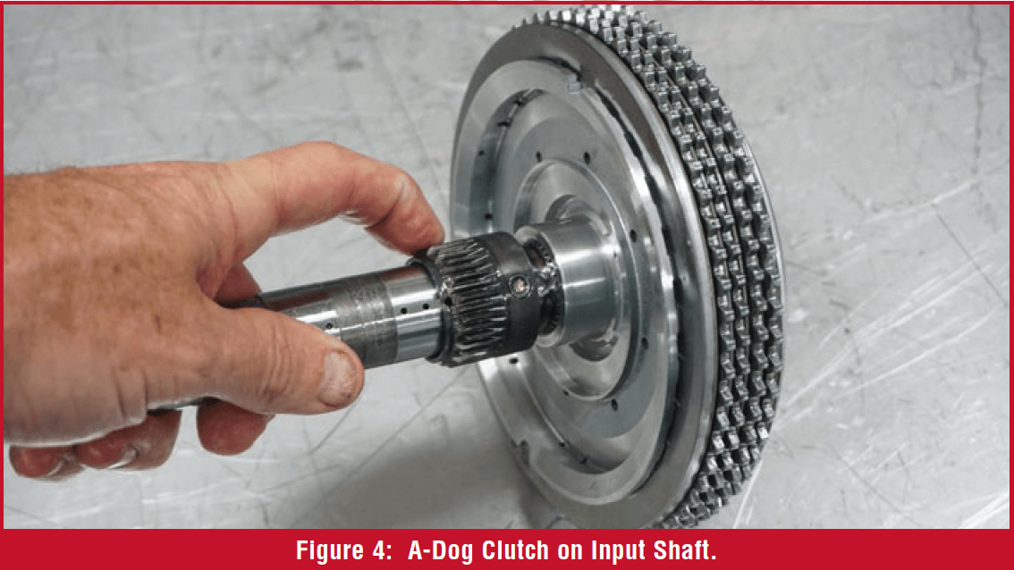
Two of the multiple disc clutch assemblies (B and E) deliver input torque to the gearset, and two of the clutch assemblies (C and D) hold a part of the gearset to the case. The A-dog clutch (figure 4) allows the input shaft to drive the rear large sun/small internal gear assembly. The F-dog clutch (figure 5) allows the front and middle sun gear to be held to the transmission case through the output gear support.
REBUILDING PARTICULARS
The 9HP48 is not a complicated transmission to rebuild. Upon disassembly, the feed tubes behind the valve body give a bit of resistance to valve body removal. The feed tubes are fairly obvious regarding their locations, and they are responsible for supplying oil pressure to the clutches, TCC, oil pump, and lube circuits.

It’s a good idea to air check the clutches upon disassembly. Figure 6 identifies the clutch passages in the case. The F-dog clutch leaks a lot until the dog’s piston shuttles, then it’s pretty tight. The F-dog clutch on the units used for this article didn’t like to shuttle unless air pressure was at 60psi or higher. That might be because the units haven’t been in use and are brand new. After applying a few times, the F-dog slams strongly back and forth when switching between the on and off passages. The A-dog ON clutch circuit also leaks quite a bit, but once it shuttles, it quiets down and seems more solid. It’s good practice to air check these before disassembly to get a reference on what you might expect when air testing the transmission after assembly.
BEARING REMOVAL
 It is necessary to remove the transfer gear bearing from the case in order to remove the C and D pistons, housings and clutches. There are reliefs cut in the case to allow the 2-jaw puller to grab under the inner race of the bearing. Position the puller in the correct spot or the bearing cage will likely get damaged (figure 7).
Like most transmissions, there are several special tools identified to overhaul the 9HP48. Miller clutch return spring compressor 8901a along with extension fingers 10428a are designed to compress the clutch housing to allow snap ring removal and perform some clutch clearance checks. The combination of these tools cost over $450.00, which is pretty expensive, but the tools are universal and can be used on a variety of transmissions.
I decided to use existing components found in the shop to substitute for the tool. A 6L80 1-2- 3-4 pressure plate fits the D-clutch housing perfectly and a broken reaction sun shell from a 4L60E stands perfectly on the 1-2-3-4 pressure plate. Bolt a cross bar to the case using the short bellhousing bolts. Try to get the crossbar as centered as possible to allow the housing to compress the piston return spring evenly. The housing will compress about 1/8” to provide enough clearance to remove the snap ring (figure 8).


The snap ring might be difficult to remove, because there isn’t a nice pry tab on the ends of the snap ring and it might spin around in the groove while trying to remove it. On a few lab units, I pressed down on the housing to relieve tension on the snap ring, then spun the snap ring in the housing to position it where I can drill a hole through the housing between the snap ring openings, then spun the snap ring over the hole, and used the end of the drill bit and a pair of plyers to pop the snap ring out (Figure 9).


Once the snap ring is out and the clutch return spring tools are removed, the o-ring seal around the housing will likely fall into the snap ring groove preventing the housing from easily pulling out. Creativity helps remove the housing (figure 10). As you can imagine, when installing this housing, apply a good coating of trans gel to the o-ring and compress the housing as evenly as possible to avoid cutting the seal.
The service information states that the C-clutch piston return spring requires Miller tool 10507a, which is only $57. This tool would be worth purchasing, but it can be made using components found around the shop as well. The 6L80’s 3-5-R steel teeth are spaced perfectly for this task. To make this tool, take the 3-5-R steel and grind out two out of every three teeth. You’ll have to take a little more material out between the teeth, but the spacing works out perfect (figure 11). I welded it to a backing plate to provide additional stiffness. This tool is unique, because it must reach between the piston slots to press down on the piston return spring and provide enough room to remove the snap ring. This process is necessary to remove the C-clutch piston for cleaning, inspection, and seal exchange.
OIL PUMP
 The oil pump is a dual-output vane style pump and it is preloaded into the pump housing. To remove the pump, use a set of welding clamps to compress the pump shaft into the housing. This will release the tension on the snap ring (figure 12). Once you remove the pump and disassemble it, you will notice the dished back plate that serves to preload the pump in the oil pump housing. Mark the pump components as you disassemble them to ensure proper assembly. The pump is not idiot proof and can be easily misassembled. If you look closely at figure 13, there is a raised lip that the pump body follows perfectly. If the pump is 180° off, the raised lip won’t follow the pump body, as shown in figure 14. The Precision International rebuild kits provide a replacement e-clip for the pump in case it gets lost or damaged. Use an arbor press and a O2-sensor socket to compress the dished plate enough to install the e-clip. When installing the pump into the housing, it will again need to be compressed with a welding clamp to provide enough clearance to install and seat the snap ring.
CLUTCH CLEARANCES
When checking clutch pack clearance, the service information states that all clutches need 45 lbs. of force applied while measuring the clearance. The only clutch assemblies that change more than a few thousandths of an inch are the B and E clutches, since they utilize wave plates. The C and D clutch do not use wave plates, so their clearance doesn’t significantly change with additional force.


The service manual identifies Miller tool 10429A as a “force gauge” that measures the amount of force applied to a clutch pack when checking its clutch pack clearance. This tool costs about $135 and measures up to 700 lbs of force. With a lathe, the tool can be made using some steel pipe and solid stock. A 1 sq. in. hole is right at about 1.130” diameter, so bore a hole in a pipe to that diameter and machine out two plugs with two o-ring grooves to fit in each side of the pipe. Next, drill and tap for a pressure gauge to fit on the side of the pipe. Lastly, fill the pipe with ATF and thread in the gauge (figure 15).

After making the force gauge, it was surprising to see that the B and E clutch both changed exactly .017” with 45 lbs. of force applied. This was true of four different lab units disassembled. Remember that these lab units have no mileage, and it’s likely a transmission with many miles will have a wave plate that defects a different amount.
CLUTCH CLEARANCES – CASE CLUTCHES
Checking the clutch clearance on the C-clutch is straight forward. Place the force gauge on the backing plate, apply 45 lbs. of force, and measure the clearance between the snap ring and the backing plate with a feeler gauge (Figure 16). An opening in the case provides access to the clutch pack for measurement. The clearance specification is .030 – .045” for 3-disc clutch assemblies and .020 – .035” for 2-disc clutch assemblies and it is adjusted by a selective snap ring. The clutch clearance specifications listed in this article were found in FCA service information. As mentioned previously, adding force to this clutch assembly didn’t significantly change the clutch clearance, likely because this clutch doesn’t use any wave/dished plates.
 The D-clutch requires a couple measurements. First, measure the distance between the case lug, where the backing plate rests, and the bottom of the snap ring, which retains the D-clutch housing. Write this measurement down. It represents the total space available for the D-clutch components. The example in Figure 18 shows the distance between the case lug and the bottom of the snap ring is 2.348”. As a service hint, don’t fully install the snap ring. Leave one end of the snap ring out of the snap ring groove to allow easy snap ring removal after the measurement.
Next, take the D-clutch housing, piston, clutches and steels to the arbor press, apply 45 lbs. of pressure to the assembly, and measure the total thickness. In the example provided in figure 19, the measurement was 2.306”. To determine the clearance, subtract the thickness of the clutch and housing assembly (ex 2.306”) from the total available space (ex 2.348”). The result is the clutch pack clearance. In the example provided, the calculated clutch clearance is .042”. The specification for the D-clutch is .040 – .059” and it is adjusted with a selective backing plate. Again, the clutch pack total measurement didn’t change significantly with force applied because this clutch assembly also doesn’t use wave/dished plates. 
CLUTCH CLEARANCE – INPUT CLUTCHES:
Because of the design of the backing plate, the E-clutch has no room for a feeler gauge to check clutch clearance. A 4L60E 3-4 clutch apply finger assembly contacts the backing plate perfectly. This gives a nice surface to measure clutch movement. Use a dial indicator on the top of the 4L60 3-4 apply fingers to measure the amount of clutch clearance by prying up on the backing plate with a screwdriver or pick. Record this total measurement. In this example shown in figure 19, the measurement was .034”. This measurement represents the total clearance of the clutch with no force applied.


Next, place the force gauge on the 4L60 3-4 apply fingers and measure the amount of negative deflection as you place 45 lbs. of force on the E-clutch assembly. In this example shown in figure 20, the dial indicator measured .017” of clutch compression (the dial moved -.017 from the zero point). To figure the overall clutch clearance, add the total movement without force (ex .034”) to the total amount of deflection with force applied (ex .017”) and the result is the clutch clearance (ex .051”). The E-clutch specification is .050 – .070” and it’s adjusted with a selective snap ring.
When checking the B-clutch clearance, completely assemble the B-clutch housing, piston and clutch assembly but leave the input shaft out. Use the arbor press with a force gauge and the 4L60 3-4 apply fingers to apply pressure on the clutch backing plate. Measure the clearance between the backing plate and the step in the housing where the backing plate normally rests (figure 21). The B-clutch clearance is .050 – .070” for transmissions with three double sided clutches and two single sided clutches. The clearance is .040 – .060” for transmissions that use two double sided frictions and two single sided frictions. A selective backing plate adjusts the B-clutch clearance.
With a few special tools, either purchased or made, the ZF 9HP48 is a straightforward and simple transmission to overhaul. Who would ever think that nine forward gears would be possible with just six clutch assemblies? This article focused on the mechanical aspects of this transmission. Keep your eye out for another article discussing the hydraulics, valve body and electrical side of this transmission.


