
In last month’s article, we shared a detailed evaluation of the Ford F-150’s transmission thermal management system. In that article, we collected temperature data from the coolant and oil sides of the transmission cooler (heat exchanger) and temperature and electrical operation data from the Coolant Control Valve (CCV). Figure 1 shows the layout of the 2019 Ford F-150 10R transmission’s oil cooling system. The goal of part one was to understand what “normal” looked like regarding temperature and CCV activation. The labels on Figure 1 indicate where we installed temp sensors to monitor oil and coolant temperatures. 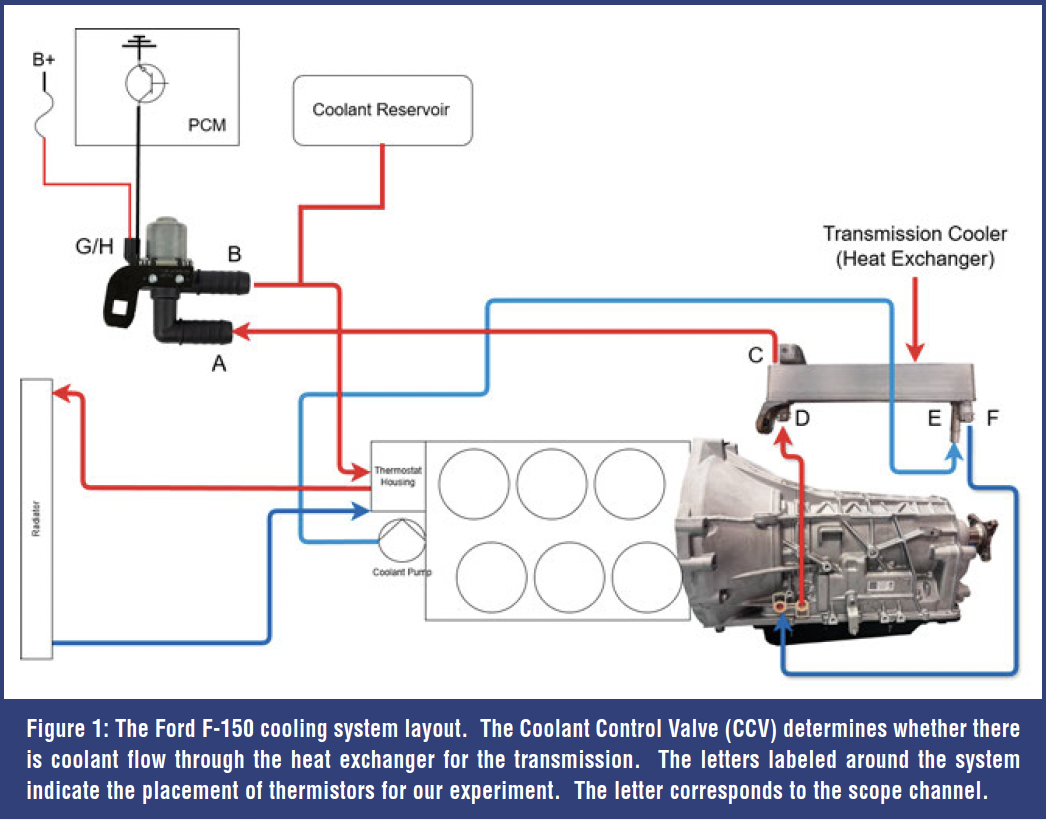 This article will explore the effects of two failures and compare the Ford 10R thermal management system with the GM 10L cooling system.
CCV STUCK CLOSED
As an experiment, we used a scan tool to force the CCV valve closed, preventing coolant from flowing through the heat exchanger (Figure 2). As expected, the transmission took a very long time (>1hr) to reach an operating temperature of around 200 degrees F. Surprisingly, it never ran hotter than normal. The test drive followed the same route as the baseline test, mostly low-load driving except for some hills. For the most part, there were very small differences between the inlet and outlet temperatures of the coolant and oil ports because there was no coolant flow.![]() The heat exchanger was simply working as a radiator with only surface airflow. If you notice the voltage jump (channel H) for the CCV, Kristy toggled the solenoid with the scan tool to ensure it was working and properly controlling coolant flow.
The heat exchanger was simply working as a radiator with only surface airflow. If you notice the voltage jump (channel H) for the CCV, Kristy toggled the solenoid with the scan tool to ensure it was working and properly controlling coolant flow. 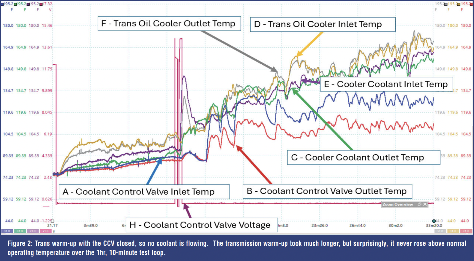 After the CCV valve toggled, the CCV inlet and outlet temps matched, and the cooler coolant inlet and the trans oil outlet temps spiked. That short duration of coolant flow allowed for a quick heat transfer from a short pulse of hot engine coolant.
You might notice that the temperatures measured at the CCV ports were much lower than those at the heat exchanger outlet, even though the heat exchanger outlet should be the same as the CCV inlet. We theorize that, since the thermistors are taped to the plastic CCV ports rather than to the aluminum heat exchanger surfaces, the physical parts experience different temperatures due to differences in material thermal conductivity. 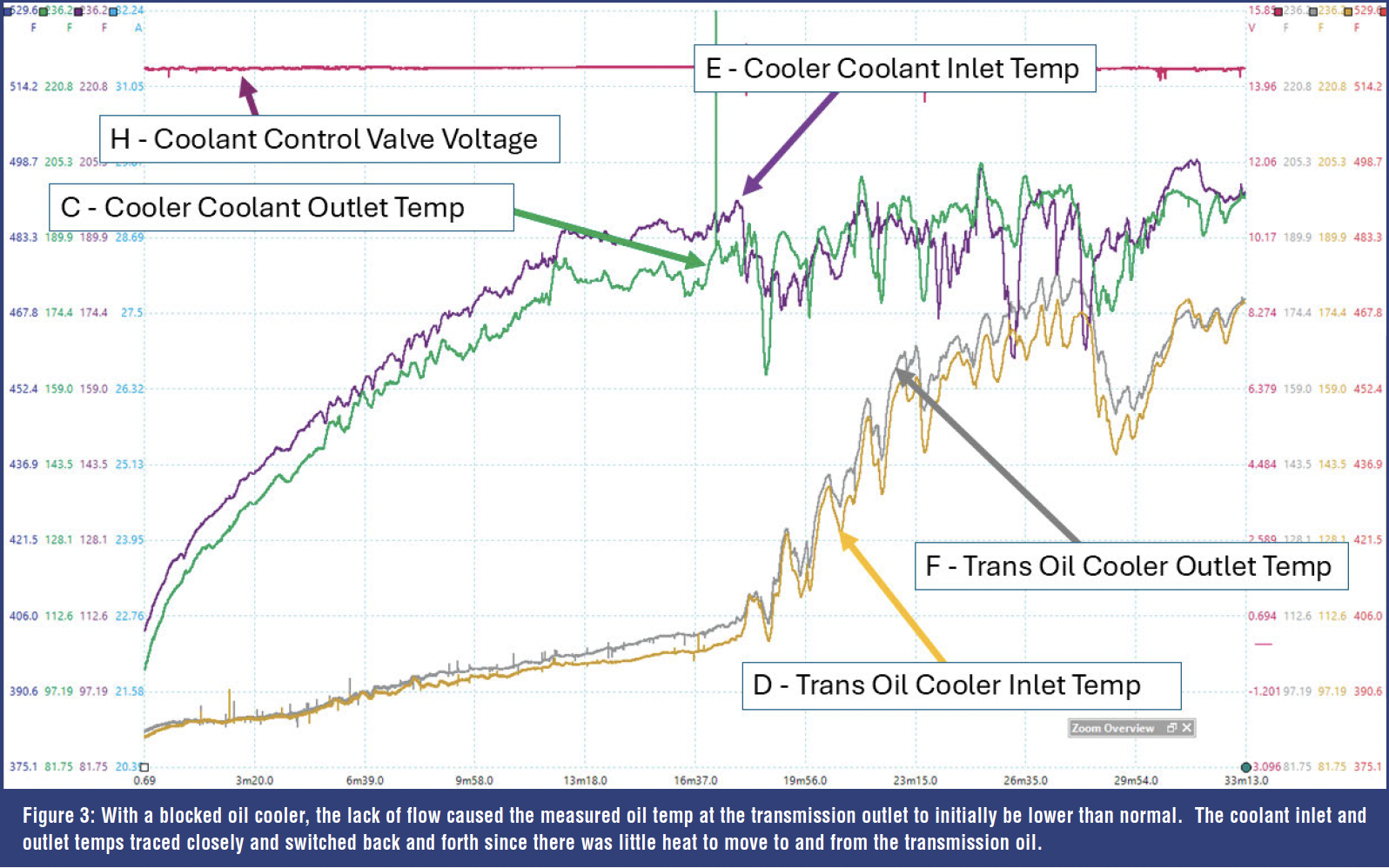 We verified our thermistors were working properly on the CCV. Regardless of the different measurements between the CCV inlet and heat exchanger outlet, the temperature split when the CCV is blocking shows the division between engine-side coolant and transmission-side coolant in the circuit, proving the CCV is blocking coolant flow when energized, as it should.

RESTRICTED OIL COOLER
To simulate a restricted cooler, we clamped off the rubber oil line leading into the heat exchanger. This prevented oil from flowing through the cooler. 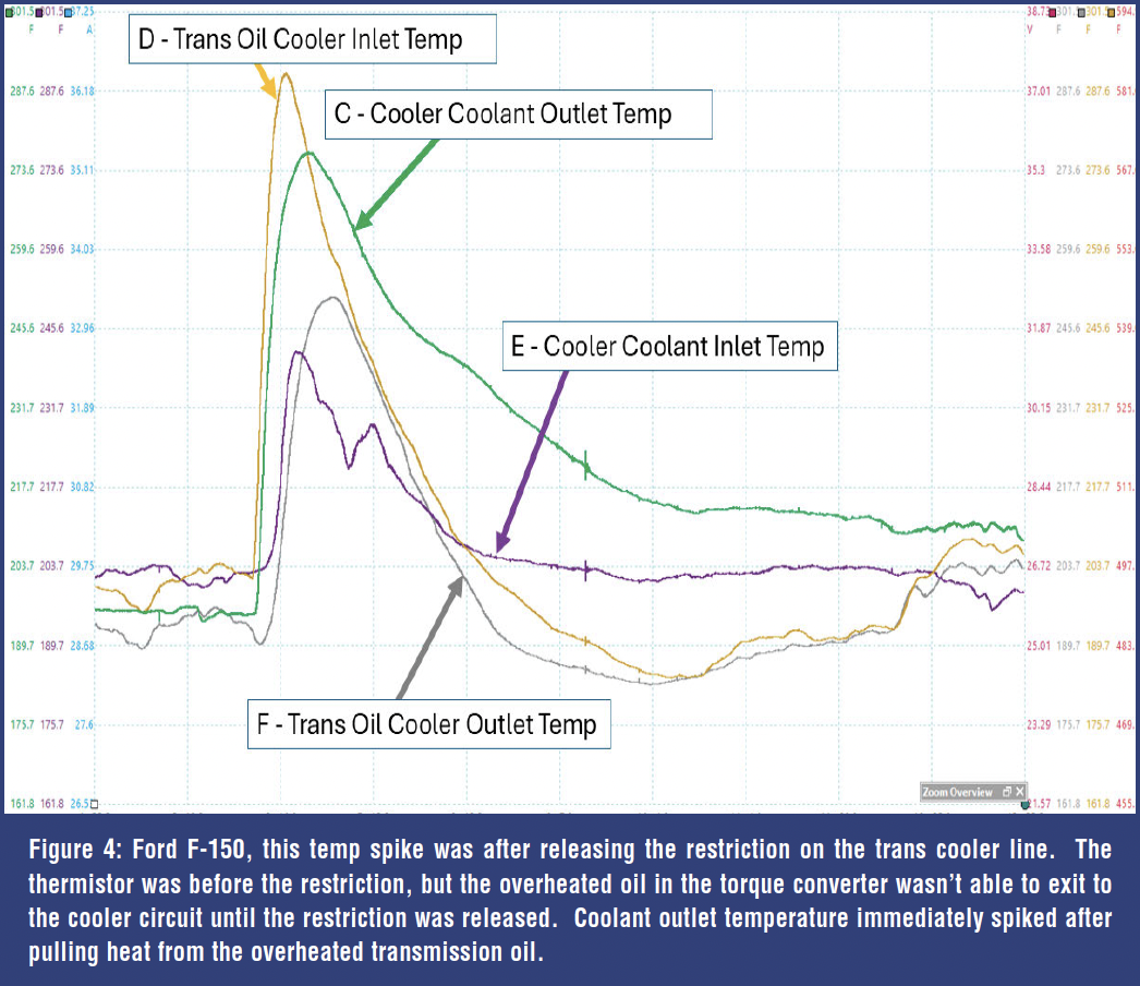 When reviewing the scope captures in Figures 3 and 4, note that, when compared to a normal drive cycle, the oil temperature was initially low and the coolant inlet and outlet temperatures changed only slightly (Figure 3). There’s no flow to aid in heat transfer. The oil temperature eventually ran over 200 degrees F. After the restriction was removed, oil temperature spiked (Figure 4) and then transferred heat to the coolant, which also spiked. This overheated fluid was trapped in the torque converter, which I’m sure didn’t appreciate this experiment!
COMPARISON TO GM’S COOLING SYSTEM
SIU has a 2022 Chevrolet Silverado TrailBoss with a 5.3L engine equipped with a conventional transmission cooling system. Figure 5 shows the layout, with transmission oil directed to an air-to-oil cooler and then back to the transmission. 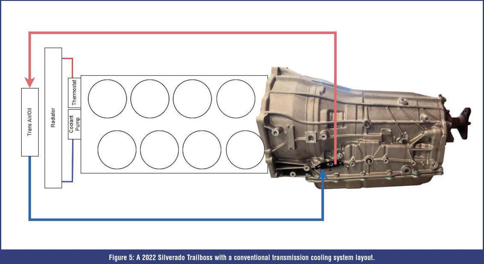 A very common low-tech setup that has been used in many transmissions for years.
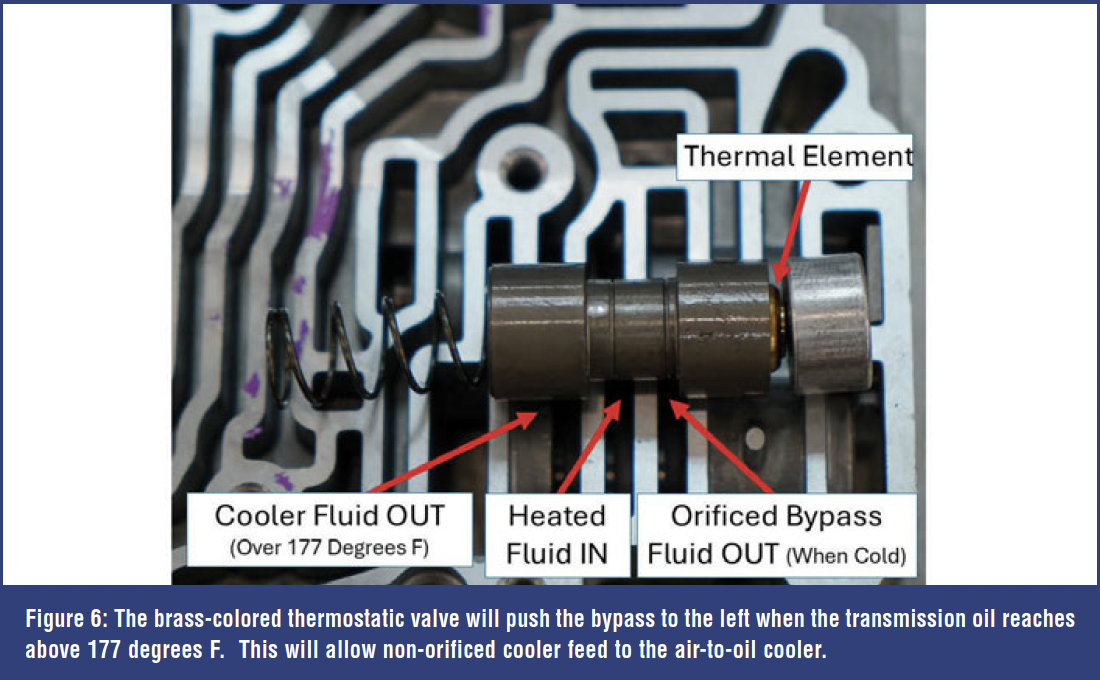
This system keeps the transmission fluid temperature at about 185 degrees when driven similarly to our Ford F-150. With the GM 10L, there’s an internal thermostatically operated cooler bypass. When checking the wax-type thermostat in boiling water, the plunger opened at about 177 degrees F. This action will move the cooler bypass valve to divert transmission oil to the cooling circuit (Figure 6).
 The GM 10L transmission took about 50 minutes on the chassis dyno to heat to operating temperature (175 degrees F) (Figure 7). Even when operating below the thermostat opening temperature, oil will still flow through the orificed feed in the cooler bypass hydraulic circuit. Unlike the Ford unit, this GM transmission took a long time to heat up when driving alone. By comparison, the Ford transmission took only about 15 minutes of driving for transmission oil to reach operating temperature. This was accomplished primarily by the engine’s coolant heating the transmission oil via the coolant-to-oil heat exchanger. When comparing Figure 7 to Figure 8, you’ll see that the drive cycle is similar (green trace = vehicle speed), engine coolant heats up at about the same pace (black trace = ECT), but the transmission oil heats up much more slowly on the GM when compared to the Ford (red trace = TFT).
 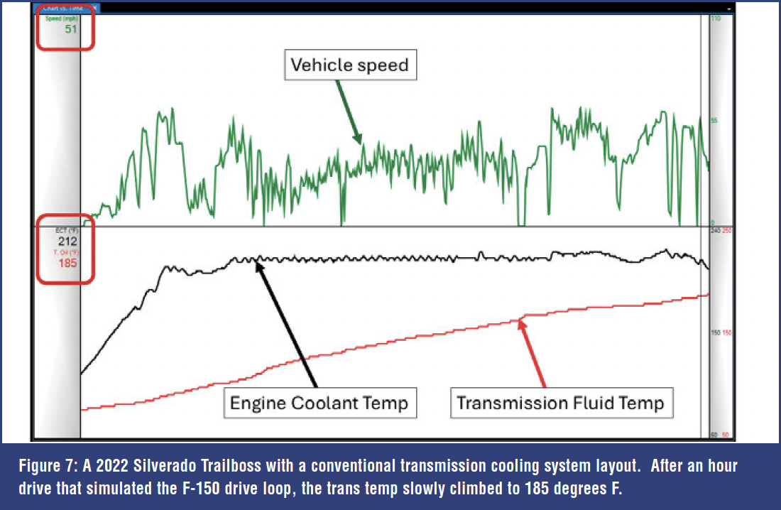 On a side note, brake torqueing the GM 10L transmission can quickly get the oil temp up to 190 degrees, so the slow cooling experienced during these tests really shows the effectiveness of the 10L’s basic cooling system, in addition to its TCC lockup strategy.
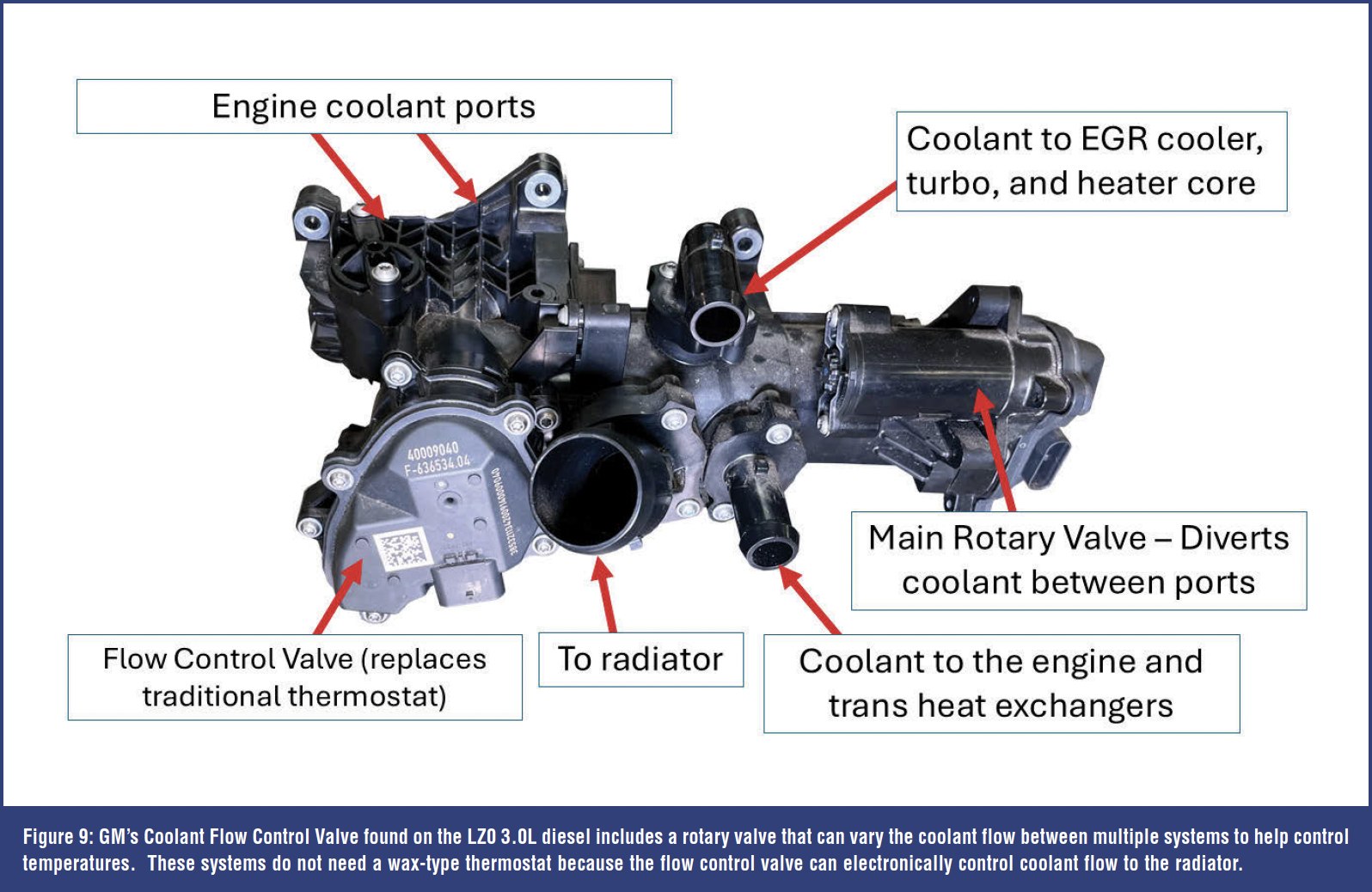
Even though our Silverado with the 10L has a very basic transmission cooling system, GM does use an advanced thermal management system on some models, such as the Silverado equipped with the 2.7L 4-cylinder turbocharged engine and the 3.0L Duramax diesel engine, and on the Cadillac CT5 with the 2.0L 4-cylinder turbocharged engine. These vehicles do not use an air-to-oil cooler like the Trailboss; instead, they transfer heat between the transmission oil and the engine coolant through a heat exchanger and a sophisticated coolant control valve. 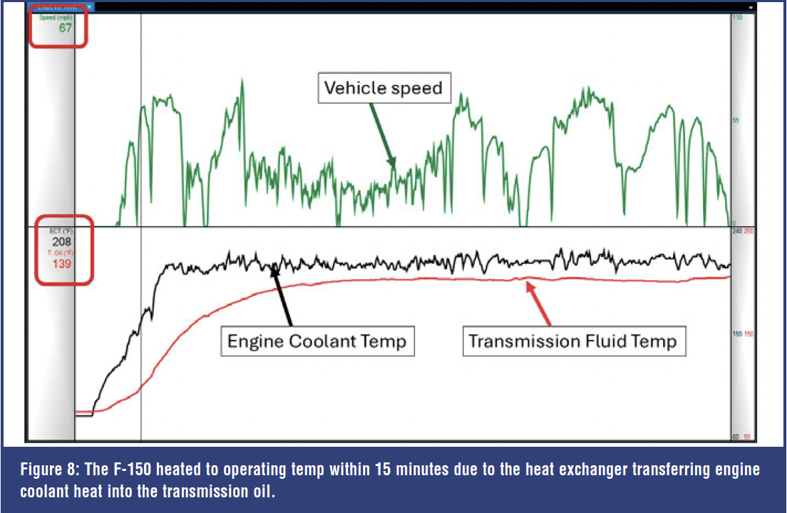 This sounds similar to the F-150, but it’s not. Refer to Figure 9, which shows an Engine Coolant Flow Valve from a 3.0L Duramax LZ0. GM uses this flow-control/distribution manifold to deliver coolant to the radiator, engine, transmission, EGR, turbocharger, and heater core.
CONCLUSION
The transmission thermal management system has advanced, as have many other systems in the vehicle. When evaluating transmission temperature concerns, we now need to consider the cooling system design, the location of bypass valves, the presence of flow control valves, and any associated computer hardware.
 There might be a tendency to simply remove or bypass these thermal management systems, but that could introduce additional problems, such as the transmission being unable to adapt (many units require trans temp to be above a certain temperature before adaptation is allowed). At SIU, we will continue to study the thermal management systems on these vehicles, so look for future articles that explore the high-tech flow-control system found on the GM 8L and 10L units.


