
The UA/UB80E transmission has been in production for over nine years now, and literally, there are just over 5 million of them on the street. These transmissions are typically paired with a 3.5 V-6 for the UA80E and a 2.5 4cyl. for the UB80E in Lexus and Toyota applications.
These vehicles are starting to show up in shops now with a number of different complaints. One of the most common is torque converter overheat or torque converter failure, causing a no move condition in any Forward or Reverse range, depending on how long the customer kept driving it. Upon fluid examination it is noticed that the fluid has been extremely overheated, black and has a burnt smell to it. At this point it is evident that the transmission has some internal issues and needs to be removed from the vehicle.

After the transmission is removed, the torque converter is removed from the transmission, and it is noticed that the torque converter has been overheated and is quite discolored. At this point, even before disassembling the transmission, blame would be placed on the torque converter as the main failure point, which is a coin toss at this time. The real question is: did the torque converter fail because of a converter feed or converter charge issue, or did it fail because of an internal torque converter issue? In order to answer this question, we need to know some specifics about this torque converter and how it is connected to the lube and cooler circuits.
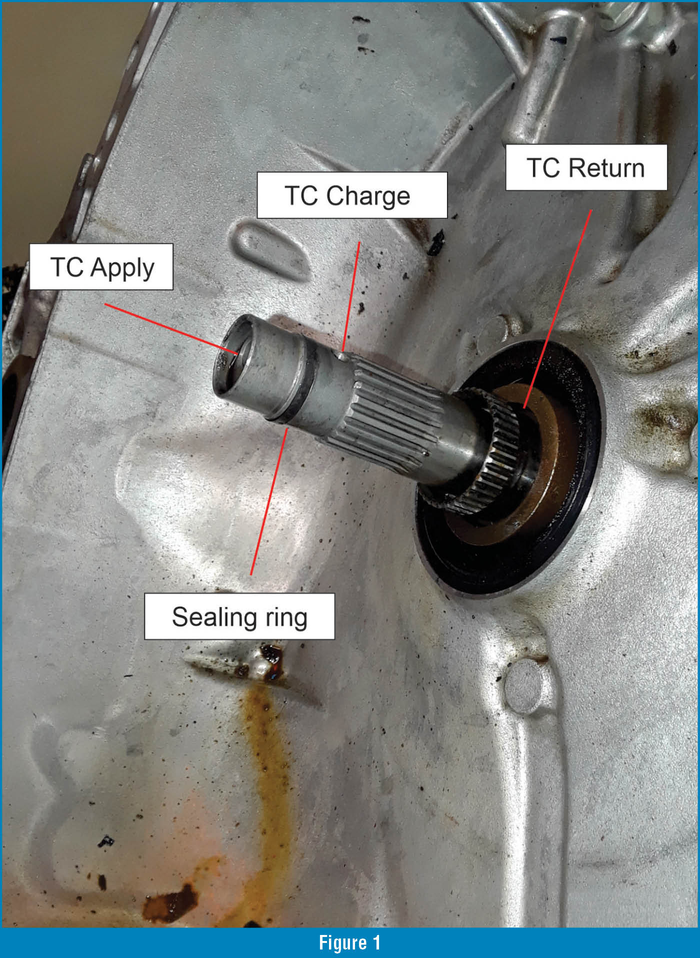
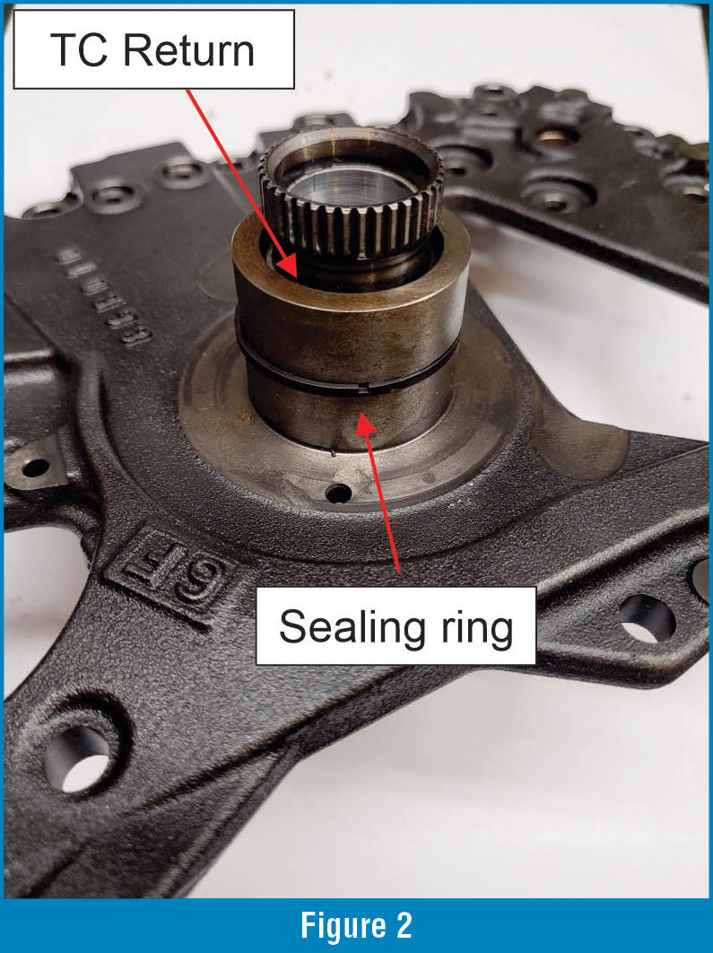
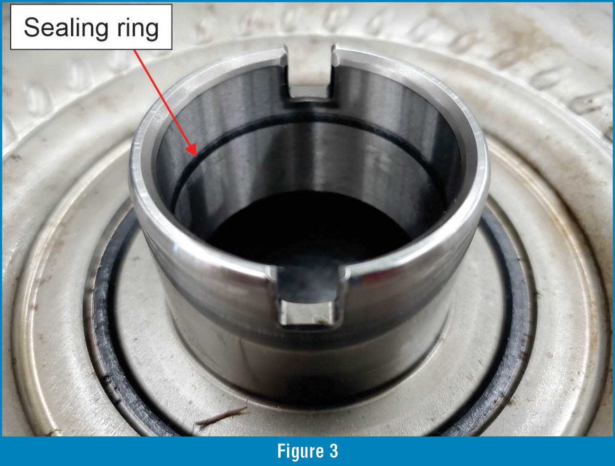
The UA/UB80E torque converter is a three-path type. It utilizes a converter charge, a converter return and a separate torque converter clutch apply passage. Figure 1 shows these passages and how they are ported on the input shaft and stator. Figure 1 also shows a main sealing point in the sealing ring that separates the TC charge and TC apply circuits. Figure 2 shows a sealing ring that is near the base of the stator shaft that seals into the converter hub as shown in Figure 3. Leakage in these sealing rings can cause low converter pressure/charge and could even cause a stalling condition or no torque converter clutch apply as well. Inside the torque converter there are other items that can cause overheat and converter failure. If you work in a shop that rebuilds torque converters, you can have the converter cut open and verify the internals in the following figures.

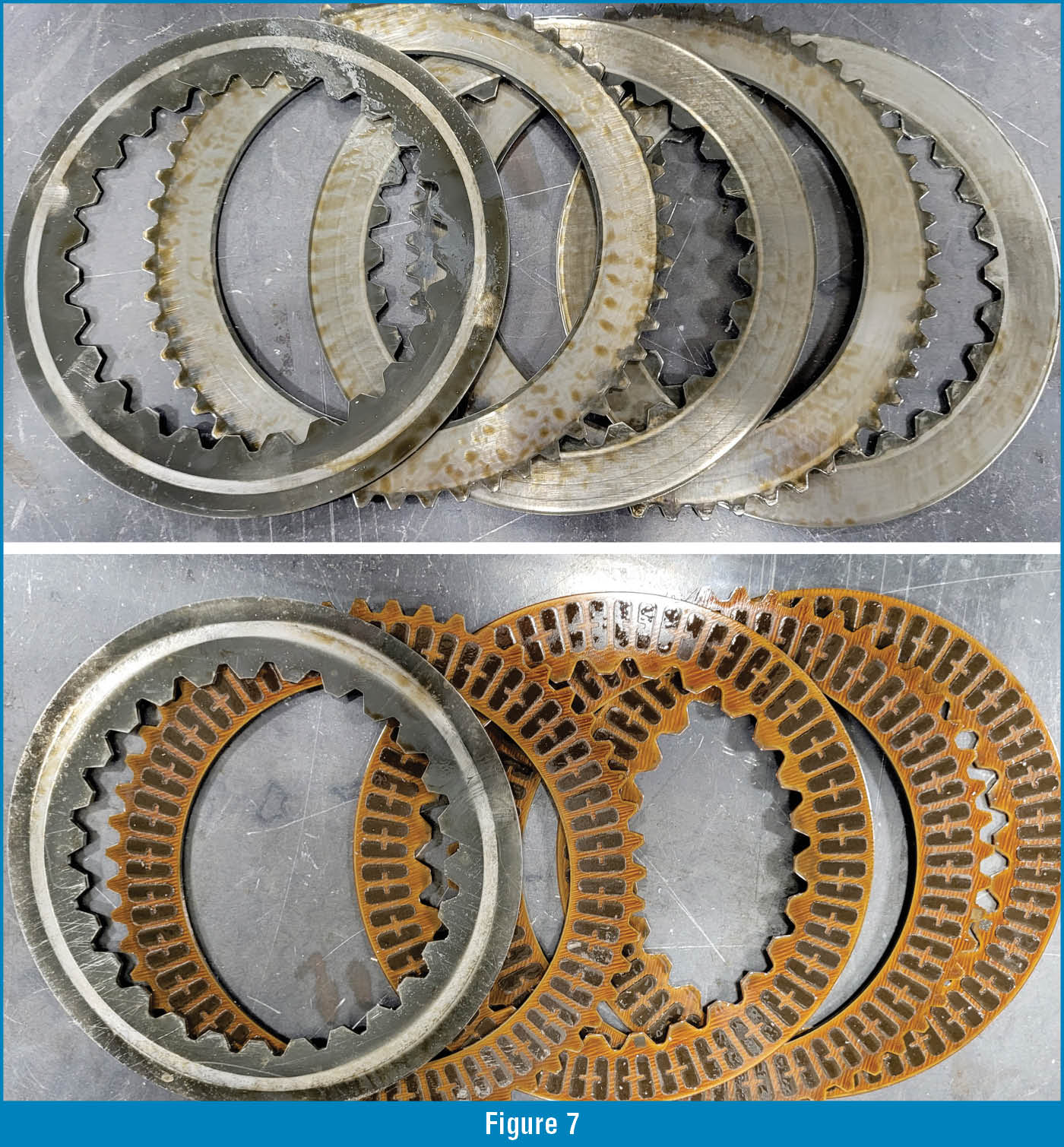
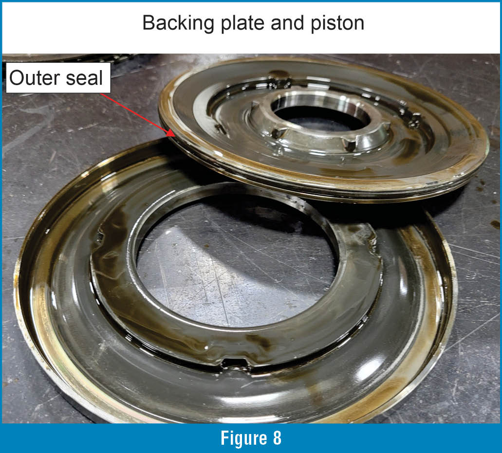
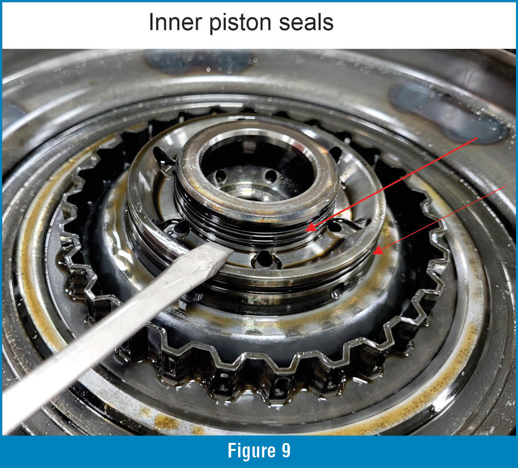
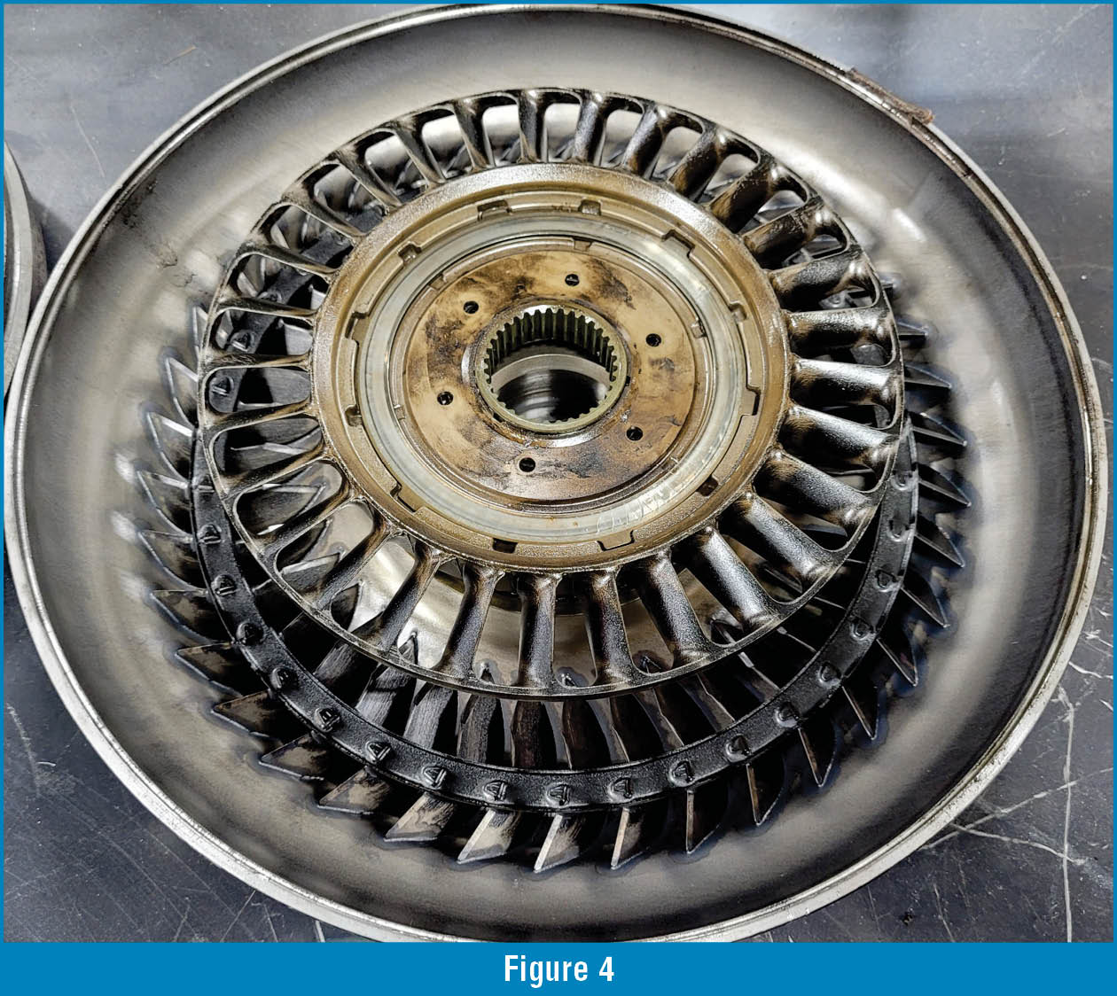
Figure 4 shows a disassembled view of the torque converter and the location of the stator one-way diode. This diode commonly fails in the locked position and can no longer freewheel, as it should after takeoff. This can cause overheat and eventual converter failure. Note: Figure 4 also shows residue of the overheated fluid on the impeller and stator assembly.
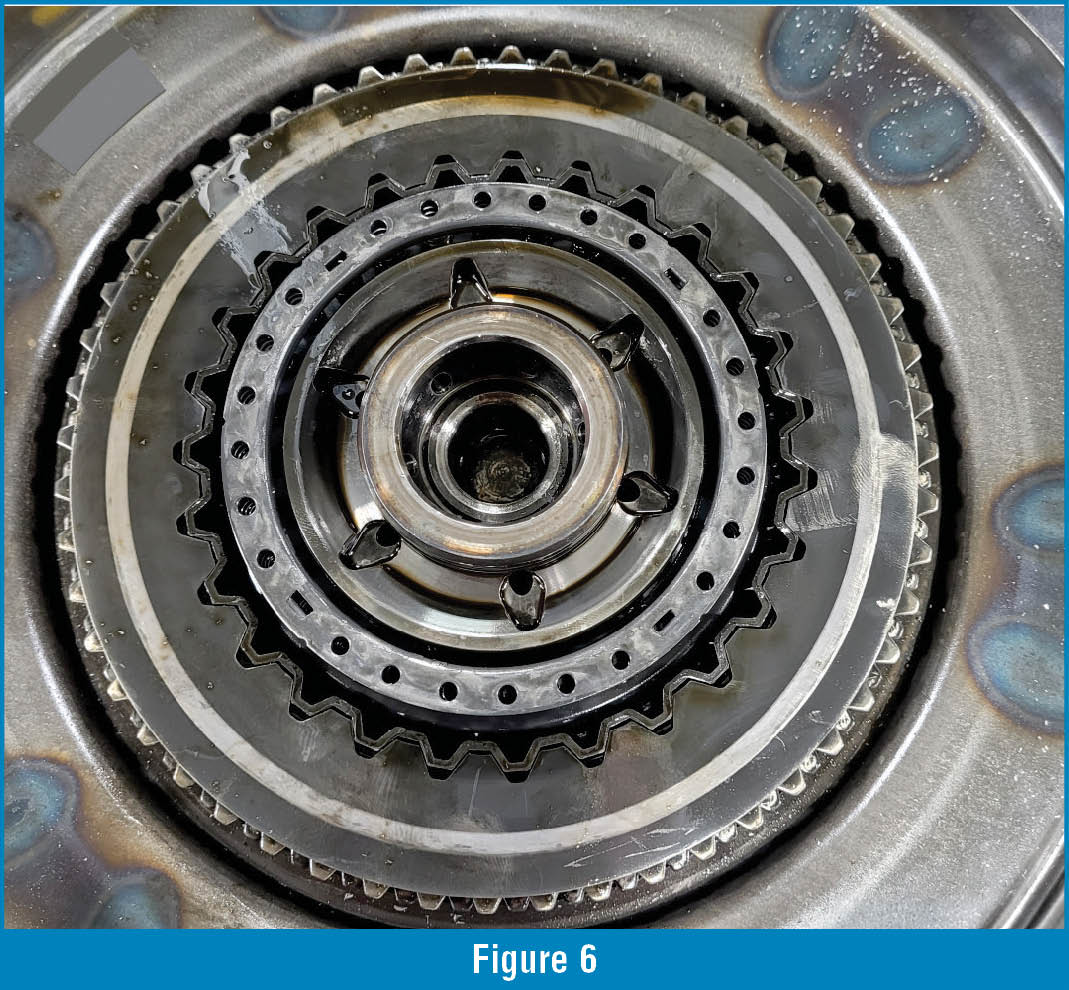
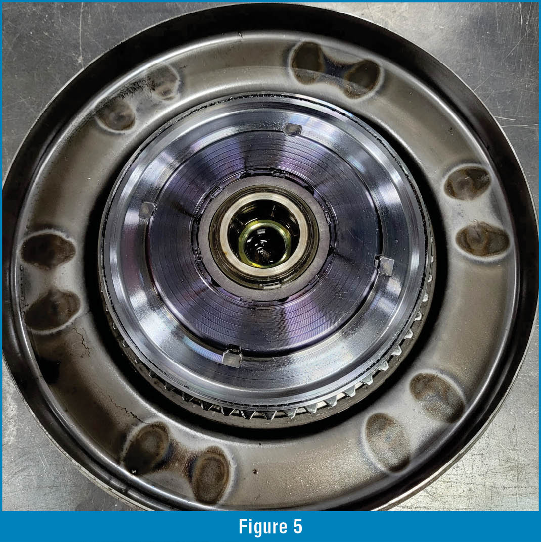
Figure 5 shows the location of the torque converter apply piston and backing plate, which are located in the torque converter cover. This piston assembly is held in place by a snap ring and a washer that is swaged in place, which helps prevent the snap ring from jumping out of its groove with centrifugal force. Once the washer and snap ring are removed, the piston assembly can then be removed (Figure 6). Below the piston assembly, the return spring and single sided clutch assembly can be removed (Figure 7).
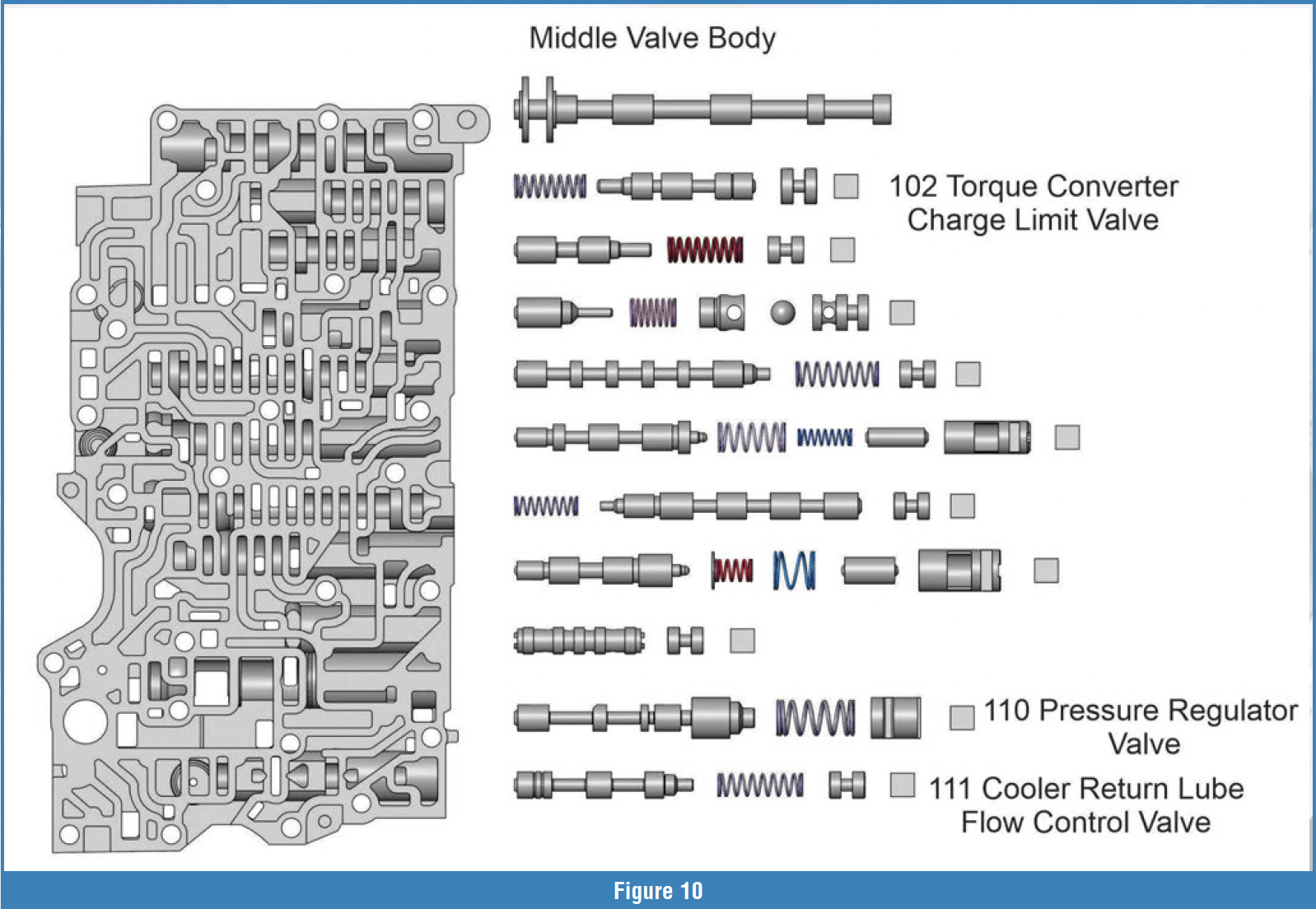 Figure 8 shows the sealing point for the torque converter apply piston outer seal and Figure 9 shows the location of the of the piston assembly two inner seals that are in the converter cover. Leakage in these piston seals will most likely cause TCC slip codes or no TCC apply, which will be evident in the single-sided clutch, as the linings will be burnt or discolored and the steel plates will be glazed or burnt as well.
If no issues are evident inside of the torque converter, then the next area to investigate would be the valve body assembly, as this is where the TC feed circuits originate. Figure 10 shows the middle valve body section. The valves related to the converter circuits are the pressure regulator valve, the converter charge limit valve and the lube flow control valve.
 The pressure regulator valve, in bore number 110, is the primary feed for all circuits, we will want to look for wear on either end of the valve and that the valve is free in the bore.
Figure 11 shows the converter charge limit valve, bore 102, in a cross-sectional view. This valve keeps a constant pressure in the charge circuit so the converter is not over-pressurized. Look for wear at the bore plug end of the valve, a loose fitting or leaking bore plug and any sign of side loading in the bore.
The last valve in the middle valve body section to look at is the cooler return lube flow control valve, which is in bore 111.  This valve directs cooler return oil based on engine load and line pressure/SLT output. Figure 12 shows the position of this valve at lower line pressure conditions and how it connects cooler return pressure back to the sump. At higher line pressure, the passage to the sump is closed off until line pressure drops. The fact that this valve is connected to SLT output makes this valve very active. This valve has been known to wear at the inboard spool, which can create elevated temperature and also a loss of SLT pressure, as SLT pressure will leak past the inboard spool and go to the sump, which causes insufficient pressure rise. Insufficient pressure rise will cause clutch failure as shifts will begin to slide as the clutches will not be able to hold.
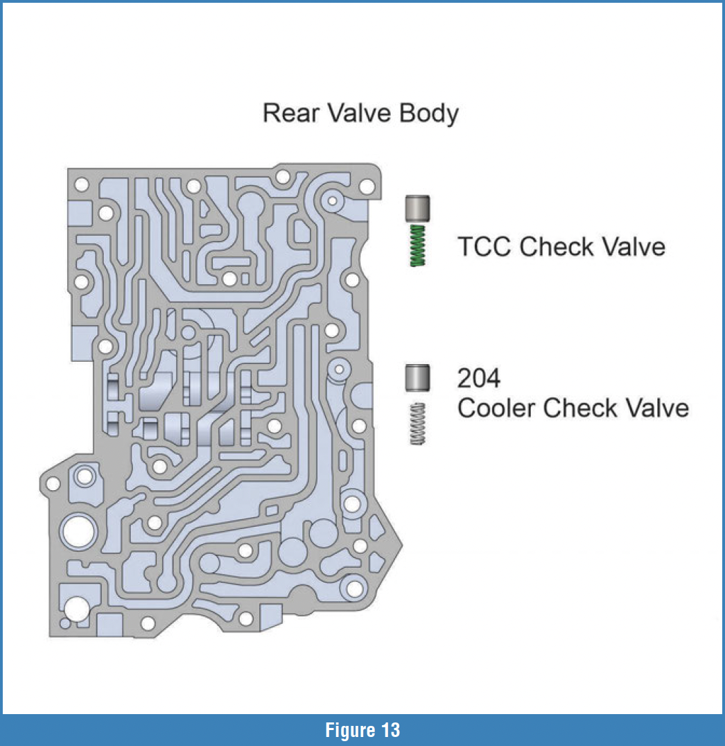 One other area that can cause cooler issues or overheat is in the rear valve body (Figure 13). There are two pistons and springs in ID numbers 203 and 204. These pistons tend to wear a ledge in the rear casting and can get stuck, which can cause low cooler pressure or low converter pressure.
In closing, torque converter overheat and/or failure does not always have to stem from a converter failure. Valve body issues can create issues like this as well. Sometimes it requires quite a bit of digging to find the root cause, but it is worth the time!


