
Diagnosing today’s modern automatic transmissions can be challenging, to say the least. We have gone from a simple two-speed transmission controlled by a simple hydraulic system to a 10-speed automatic transmission with a highly sophisticated electronic, computer-controlled system. Fortunately, the diagnostic codes have improved significantly. Most TCM/PCMs use smart drivers that can detect an open, a short to ground, or a short to power in the circuit, which makes it very important that we pay close attention to the diagnostic codes and their descriptions provided by the manufacturer.
We had a 2019 Ford Ranger with a 2.4 engine and a 10R80 transmission that came in neutralizing at stops and then engaging Drive again, with the following codes: P0748, P0768, P0868, P0962, P0982, P2700, and P2703.
P0748 “Pressure control Solenoid “A” Electrical”. The description mentions that this code will illuminate the wrench light in conjunction with either/or codes P0960 “Open circuit in the LPC Solenoid circuit”. P0962 “Pressure control Solenoid “A” control circuit low. This DTC indicates “short to ground on the LPC Solenoid circuit” or P0963 “Short to power on the LPC Solenoid Circuit”. We had P0962 indicating a short to ground was at fault.

 P0768 “Shift Solenoid “D” Electrical”. The description mentions that this code will illuminate the wrench light in conjunction with either/or codes P0982 “Shift Solenoid “D” Control Circuit low”, which indicates a “short to ground in the SSD Circuit”, P0983 “Short to power in the SSD Circuit”, P097D “Open circuit on SSD Circuit”. We had P0982 “Short to ground in the SSD Circuit.”
P0868 “Transmission fluid pressure low”. Under Fault trigger conditions, it states: “This DTC indicates a non-electrical fault causing 2 or more clutches to fail to apply. The PCM understands this as more likely caused by low line pressure. The transmission fluid was low, causing Clutch A to disengage at stop signs and to neutralize. This was corrected by proper fluid level.
P2700 “Transmission Friction Element “A” Apply time Range Performance” under Pinpoint test, a description is given as “PCM monitors Clutch application on all gears. If it detects a non-electrical Clutch application Fault, it will set a DTC. 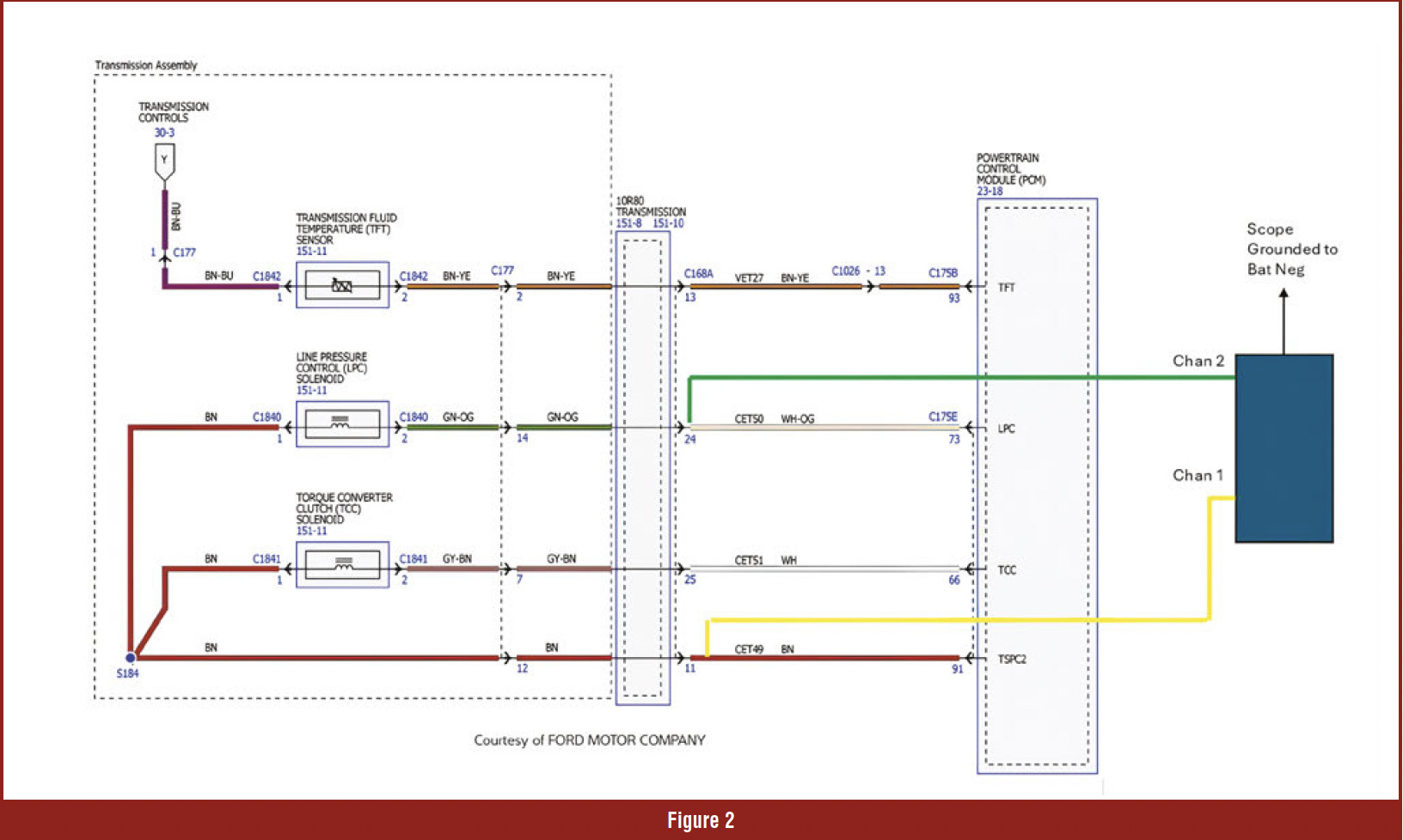 Under “DTC Trigger conditions” it states that this DTC will illuminate the wrench light in conjunction with either/or P0751 “which indicates a non-electrical fault that causes “A” Clutch to fail to apply “Shift Solenoid “A” Performance Stuck OFF or P0752 “which indicates a non-electrical fault that causes “A” Clutch to remain applied when it was commanded off”; “Shift Solenoid “A” Stuck On”. In our case we only had the P2700, which to me, the PCM was smart enough to detect that Clutch “A” was being release and applied.
P2703 “Transmission Friction Element “D” Apply Time/Range performance.” Under Fault trigger conditions, it states that this DTC can illuminate the wrench light in conjunction with either code P0751 SSD solenoid performance stuck on” or P0752 “SSD solenoid performance stuck off”. We only had P2703.
 We had rebuilt this transmission about 100K miles ago and had updated the CDF drum. We removed the transmission oil pan, replaced the filter, filled with ATF to the proper level, cleared codes, and drove the vehicle. It took a while, but only codes P0748 and P0962 set. We knew we were dealing with an electrical problem and, more specifically, a short-to-ground problem.
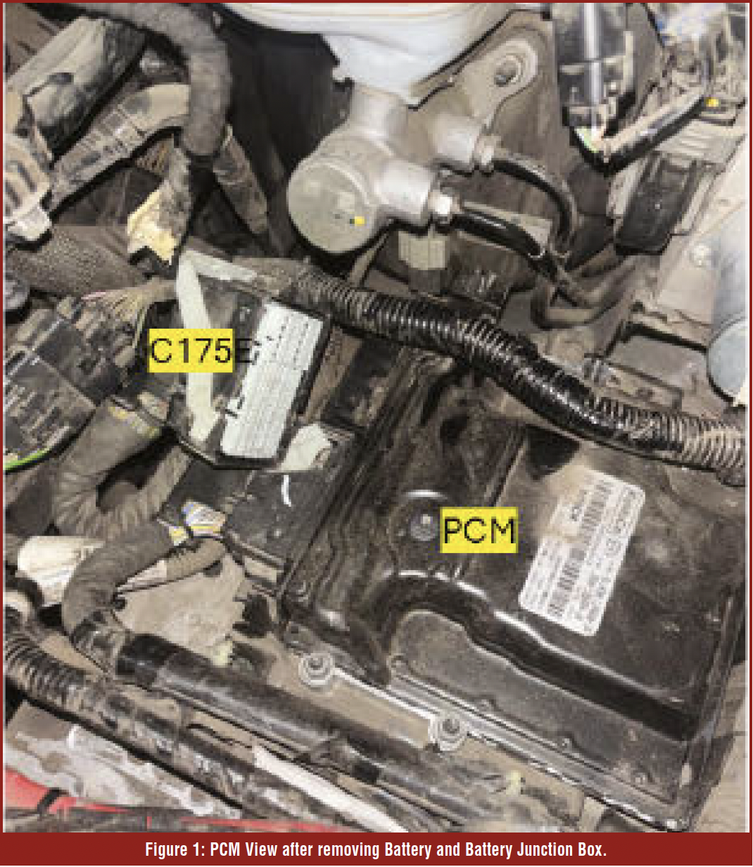
I normally like to back-probe as close as possible to the PCM, as this will reveal whether the problem is downstream of the PCM or inside the PCM, but in this case it was impossible because the PCM is buried behind the battery and battery junction box. So, I had to settle for the only place to back-probe, at the transmission connector (Figure 1).

 We connected a scope to the LPC circuit to monitor both the high- and low-side. Channel 1 (Yellow) monitors the voltage side of the circuit (Pin 11 of the transmission connector), and channel 2 (Green) monitors the control circuit side of the circuit (Pin 24 of the transmission connector) (Figure 2).
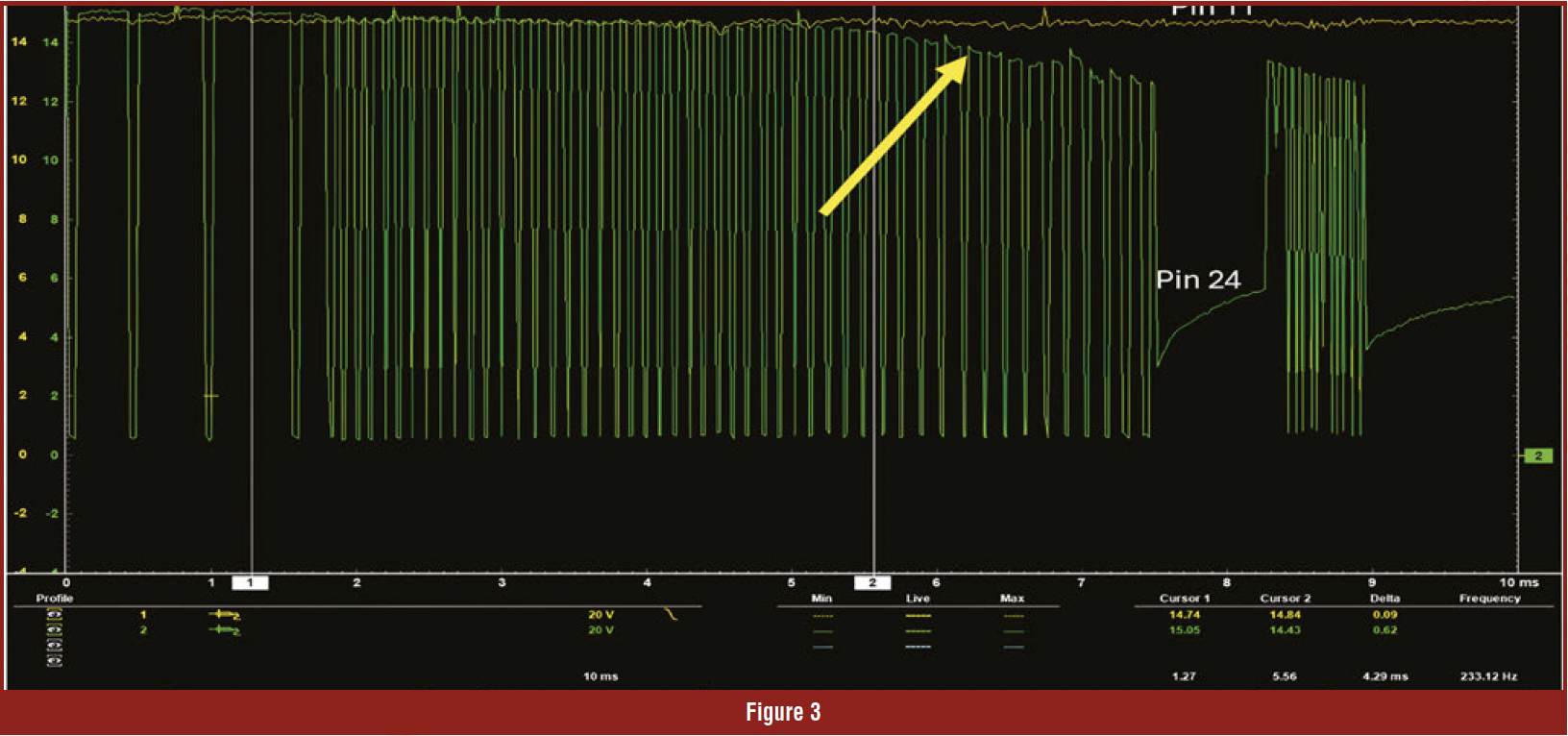
The scope proved that we had a short to ground on the control side of the circuit (Pin 24 Channel 2) (Figure 3).
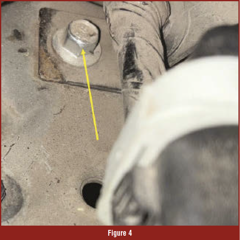
We spent hours trying to locate the short, even checking for resistance between the circuit and battery ground during the wiggle test, with no results. A decision was made to replace the PCM (They say hindsight is 20/20). 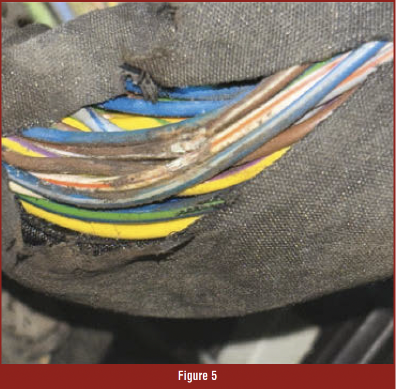 After programming the PCM, the problem was still there, and now it set the same code almost immediately. Back to the drawing board. The fact that it now set the code almost immediately led us to see that we had disturbed something when replacing the PCM. We removed the PCM and looked closely at the PCM connector C175E, with no problems found. We released the PCM harness (C175E) from the vehicle frame, and we noticed a very clean bolt (Figure 4). That told us the harness was rubbing there (Figure 5).
We had to cut open the harness of the C175E connector to see the problem.
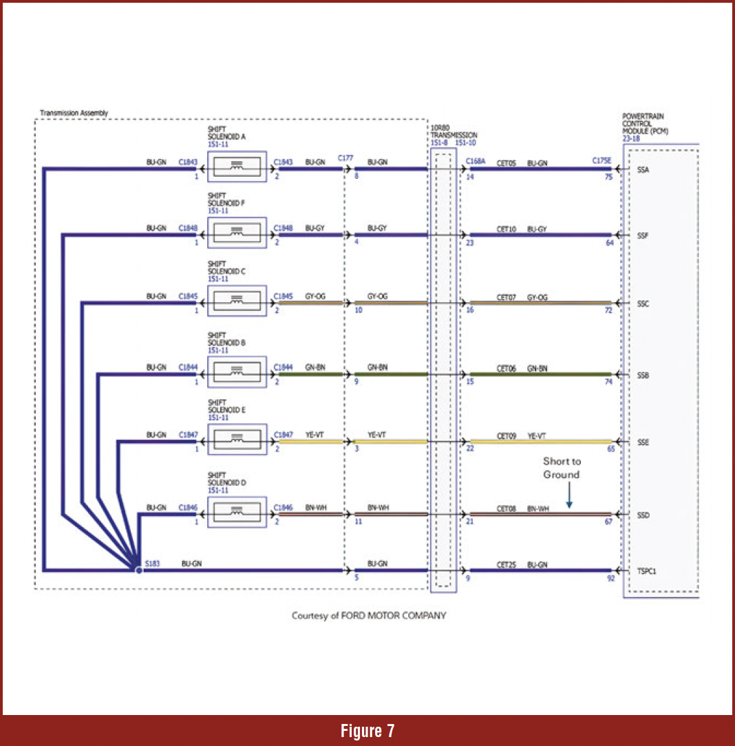
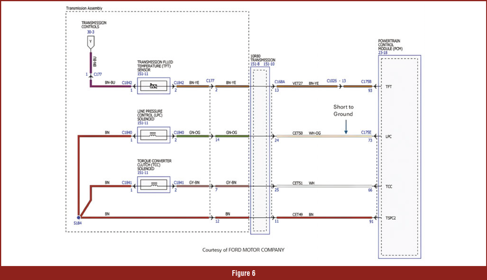 Brown/white and white/orange wires were the ones contacting the bolt, causing a short to ground. Brown/White is circuit CET08, pin 67 of the C17E connector, which is the control side of SSD, and White/Orange is circuit CET50, pin 73 of the C175E connector, which is the control side of the LPC solenoid (Figures 6 and 7).
The lesson learned. The Smart Driver was telling us that it had a short to ground on both circuits by giving us code P0748 “Pressure control Solenoid “A” Electrical”, in conjunction with P0962 “Pressure control Solenoid “A” control circuit low” and code P0768 “Shift Solenoid “D” Electrical, in conjunction with P0982 “Shift Solenoid “D” Control Circuit low.
 Looks like the Smart Driver was smarter than me. The point is: we need to pay close attention to all the codes the vehicle comes in with. In our situation, it was the vibration of the drive that would short the circuit to ground. That is why if the vehicle was not being driven on a bumpy road, the code would not set until we disturbed the C175 connector.
Smart Driver samples the circuit during PWM in the ON & OFF phases; thus, it can determine which fault conditions exist. That is, an open circuit, a short to ground, or a short to voltage. During the OFF Phase, it expects to see battery voltage present as voltage travels through the solenoid’s coil. If the voltage does not rise during the OFF Phase, then the driver knows the load is grounded somewhere else, and a short-to-ground code is set.
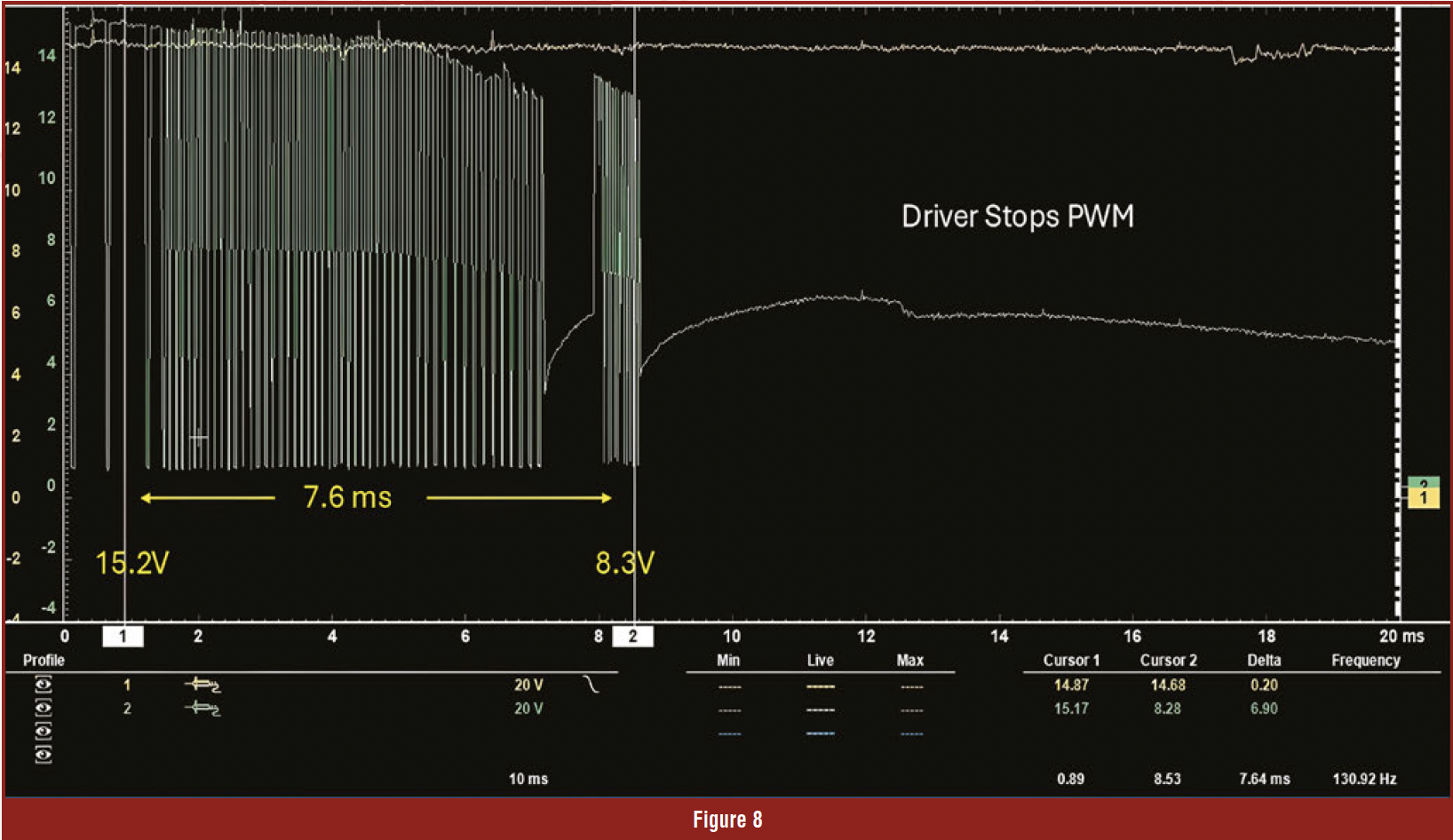 Using our example, we can see that cursor1 source voltage is 15.2 during the OFF Phase; 7.6 milliseconds later, cursor2 reads 8.3 in the same OFF Phase. Smart Driver determined that the circuit was being grounded somewhere else, so it decided to shut down the circuit and set codes P0748 and P0962. In my opinion, back-probing a PCM is no longer necessary, as the Smart Driver is doing it for us and determining where the problem lies. We just need to pay close attention to the code’s description (Figure 8).


