
Last October, I was lucky to spend a few days with Bob Warnke, the Vice President of Technical Development at Sonnax Corporation. He did the big 13+ hour drive to come to SIU so I could help him record and edit his seminar for Expo. In exchange, I gained a wealth of information regarding torque converter design, construction, operation, and diagnosis. If you haven’t already viewed some of the seminars from the ATRA Virtual Expo, I highly recommend you sign up (which you can still do) and view some of the awesome seminars. Bob’s torque converter session ended up being almost three hours of incredible tech.
I learned a ton, so I felt I had to share. In this article, I will summarize and share some of the topics I found most interesting, and hopefully, you will too!

Most of us think of the torque converter as this magical donut that lives between the engine and transmission. We put our faith in our torque converter supplier because that’s the one area of the unit we rarely get to inspect. When unboxing the reman converter, we give it a critical look through our judgmental eye; inspect the paint job, hoping it wasn’t a pressure cooker in a previous life; maybe give it a peak down through the hub and a little shake. Finally, we bless it and hope for the best.
Blessing doesn’t always work, and sometimes we end up with a dreaded TCC DTC or drivability complaint. This is the point where the blame game happens (figure 1). Is it the converter? Or some converter control, like the solenoids, valves, TCM/PCM? Or is it leakage through bushings or seals? It could be any of these things, so that’s where education comes into play. That was the purpose of Bob’s seminar and also this article!
Basic Operation:
Before getting too deep in trends, designs, failures, and causes, it’s important to understand how the torque converter operates. Here is the “explain the torque converter in less than a paragraph” version: First and foremost, understand that aside from lockup, the fluid is doing all the work in the torque converter. As shown in figure 2, the impeller (engine driven component) rotates. I then transfers the rotational energy from the impeller to the fluid, and the impeller “slings” that fluid to the turbine. The turbine is connected to the transmission’s input shaft and receives torque from that force. The turbine fins absorb the force from the fluid, and any remaining energy that is left over is directed to the stator.

During torque multiplication, the “locked” stator redirects this fluid back to the impeller in the same direction of impeller rotation. This is the basic premise of torque multiplication.  The fluid rapidly travels in a “vortex flow” where the fluid moves from the impeller to the turbine, to the stator, and back to the impeller. The momentum of the fluid redirected by the stator helps the impeller (or engine) rotate. It’s not a perfect analogy, but it’s like riding a bike with the wind at your back – you can go a little faster.
When the impeller (engine speed) and the turbine (input shaft speed) are going approximately the same speed, the torque converter enters the “coupling phase,” and the fluid makes more of a “rotary flow.”  During this condition, the left-over fluid energy from the turbine will hit the back of the stator blades. Now the stator will freewheel to prevent the fluid from bouncing back and going against impeller rotation. That’s why torque converter stators have a one-way clutch – to allow it to lock during torque multiplication and freewheel during cruising speeds.
Brazing for efficiency:
Over the years, converters have gone through a few changes. Manufacturers are making them lighter to reduce rotating mass and improve fuel economy. Many FWD converters utilize an elliptical design, as shown in figure 3. This is often termed as “squished” or “pancaked.” This design allows for a shorter bell housing and more space in the transmission for gearsets and clutches – we need to squeeze those 10-speeds in somewhere!
Some converters utilize brazed turbine assemblies where the fins are brazed to their shell. The furnace brazed turbines are stiffer, have reduced lateral runout, and are more efficient. On a non-brazed turbine, the fins are crimped through stamped slots. Figure 4 shows crimped and brazed side-by-side. The slots for the crimped turbines are not precise, and there are relatively large gaps around the crimps, as you can see in figure 5. These slots allow fluid to pass through, which reduces efficiency. Plus, as you can imagine, this design isn’t as structurally rigid as a brazed turbine. Bob mentions that the fluid that leaks through the turbine, which he calls “wash,” ultimately becomes energy loss and can increase heat in the converter.
Heat conduction:
A torque converter is the main source of generated heat in a transmission. A converter operating at stall (max engine rpm vs turbine rpm) generates the greatest amount of heat, and a converter that’s in full lockup will generate the least amount of heat. Of course, many converters today operate somewhere between no lockup and full lockup.
It’s common for the TCC to partially lock up as early as second gear (sometimes first gear). Once applied, the TCC might not fully disengage until returning to a stop or operating under heavy load. This is especially true for CVTs. The TCM programming has the TCC applied as much as possible to improve fuel economy. This is possible through sophisticated converter control programming and improved friction lining. Look at the snapshot from the Honda 10-speed (figure 6). You can see that it went into full lockup at 14mph in 3rd gear. It starts to lockup at 10 mph in 2nd gear. Once locked, you will notice the converter never released during the snapshot (figure 7).

On a side note, with some converters such as the 6L90, the low speed and low RPM lockup along with cylinder deactivation can cause additional stress on the friction lining and the damper springs/spring retainer. The damper springs generate cracks in the spring windows. There is an upgraded spring retaining plate because if this actual problem. It would be worth checking with your converter rebuilder to discuss the upgrades performed during the remanufacturing process.
TCC friction lining is going to be either a cellulose (paper) type material or a carbon material. Bob used a neat example to show how the linings handle heat. Using a DVOM, he demonstrated that the carbon lining has very low resistance between the lining and the cover, indicating that it is a conductor. Whereas the paper lining had infinite resistance between the lining and the cover, indicating that it was an insulator. The carbon lining, acting as a conductor, can transfer heat better to the cover than the paper cover, which acts as an insulator. Although thermal and electrical conduction might not follow the same rules, it’s true that carbon can handle heat better than paper. Carbon linings are woven in a fashion to allow fluid to wick through even when the clutch is applied. The wicking of fluid will allow for heat removal. Bob went on to explain that even though carbon linings are great at handling heat and slip, they don’t handle impact well. The carbon is less forgiving to uneven contact and can fracture. For example, with the 6L90 converter under load, the flexplate pads can deflect (due to a thin OE cover) and cause high spots where the friction material rides. The high spots stress the carbon friction and over time will cause lining fracturing and failure.


There are still plenty of converters that use the paper type friction lining. These converters rely on grooves cut in the friction lining and ample fluid flow to keep them cool. In figure 8, you can see the reliefs cut to allow a constant flow a fluid past the lining which will help reduce heat during partial TCC apply.
Two path/three path:
There are two main designs of torque converters based on their oil-path circuits. In a conventional two-path torque converter, there is an “apply” passage and a “release” passage. The names refer to the state of the torque converter clutch. Fluid enters the converter through the “apply” passage when the TCC is being applied (figure 9). Fluid enters the converter through the “release” passage when the TCC is released. When fluid enters the release passage, it gets directed through the tip of the input shaft and travels through the converter between the converter cover and the TCC piston. Since the fluid is traveling between the piston and the cover, it pushes the piston away from the cover, which releases it.

The opposite happens during TCC apply by reversing the fluid flow. The fluid enters the torque converter through the apply passage, which is on the turbine side of the piston and fluid is exhausted through the tip of the input shaft (figure 10). The pressure on the turbine side of the TCC piston forces the piston against the cover and the friction lining seals against the cover. Converter pressure is present across the entire TCC piston and the generated force is what applies the converter clutch against the cover. Have you ever stopped to think about how much force a typical TCC piston is applying at full lockup? Looking at this TMBX (4L60e) apply piston (figure 11), it has almost 100 sq. in. of surface area. With the TCC apply pressure at 115psi, we are getting over 11,500lbs of force! Enough to lift two of the trucks these transmissions were put in! Keep that in mind for discussion later.
As you can guess, the three path converters have an additional oil circuit. Most three path converters have two oil circuits to cycle fluid through the torque converter. Usually, the third oil path is to apply a dedicated torque converter lockup piston (figure 12). This type of three-path converter will use a multiple disc clutch assembly and a more complicated hydraulic control. Since the converter is always charged with pressure, the pressure on the TCC apply piston needs to be greater than the charge pressure in order to move. The overall clamping force on the clutch assemblies is determined by the difference between charge pressure and TCC apply pressure times the surface area. Examples of three path converters include the Mercedes 722.6/NAG, Ford 6R140, Honda 6-speed and 10-speed, and ZF 8HP.
Floating piston and captive clutch:
Converters can also be classified by their clutch design. Since the 80’s most converters use the “floating piston” design, where the TCC piston is basically a large, dampened disc that’s splined to the turbine hub. As mentioned above, the piston floats back and forth depending on the direction of oil flow. These converters are typically two-path converters where the TCC control valve simply reverses oil flow direction to switch between TCC apply and release. Although two-path designs are most common, the floating piston design can also be a three-path, like many Honda units, where the third path is responsible for controlling how much pressure exists between the cover and the piston.


Another converter design that’s gaining popularity is the “captive clutch” configuration. The captive clutch design utilizes multiple clutches or clutch surfaces to improve holding capacity. Many of these designs use a separate dedicated piston located front cover. During discussions, Bob really stressed the sensitivity of the 3-path/captive clutch regarding cross-leaks. When the clutch is released, any pressure that can leak into the clutch circuit can, through centrifugal force, cause pressure buildup and start to apply the clutch assembly. This partial application of the clutch can “crowd” the engine, which is when the clutch is dragging and pulling the engine speed down while the vehicle is at a standstill. The customer might observe this as the vehicle lunging, surging, or the engine having an erratic idle or stalling. These problems might be exaggerated when the transmission warms up as parts expand and fluid gets thinner leading to a greater chance of cross-leak.
Other problems that captive clutch designs might experience include cracked pistons, worn plate splines, or even a failed clutch housing, like on the 6R140 converter. In figures 13 and 14, the converter not only had steel plates worn into their housing splines, but the center housing welds broke allowing apply and release oil to intermix, preventing lockup. On a positive note, the 3-path/captive clutch can be air checked like a conventional transmission clutch, so the builder can verify a quality clutch apply on the bench!
Interesting facts:
Some converter pistons are designed with a 1–3 degree taper where the friction lining contacts the cover. This angle exists to allow the friction material to lay flat on the converter cover when applied with full TCC apply pressure. This made me curious on how I could check for this taper since I have about 20+ cut converters handy at the school. Bob came up with the good idea of placing plastigauge evenly spaced around the converter cover and lightly compressing the piston to the cover in an arbor press. With my first attempt, I got carried away and put my weight on the arbor press handle. I could visibly see the piston flexing, and as a result, the plastigauge was squeezed flat but even. I realized that I should press just enough to compress the plastigauge and not flex the piston in order to observe the taper. I found that with the GM JMBX (6L80) and the Ford 6F50 there was indeed a taper to the piston (figure 15 and 16). For what it’s worth, both pistons had carbon friction material. I did also test the test on the Honda 5-speed and a 62TE converter which uses paper friction material and there wasn’t any noticeable taper (figure 17).
 So why does this all matter? Well, you can imagine what would happen when the converter is not supplied with the proper pressure. Too low of pressure with a piston that has a taper and the piston won’t deflect as intended and only the outer portion of the friction lining will contact the cover, which will cause it to slip, overheat, glaze, and fail. Too much pressure, and the piston will continue to deflect and contact primarily the inner portion of the friction lining, causing it to slip, overheat, glaze, and fail. Bob had some great examples of this in his presentation.
This is a good thing to keep in mind when modifying a TCC circuit hydraulically during overhaul. If the modification increases TCC pressure, then you will want to consider upgrading the torque converter to handle the higher pressures. Remember the example of the TMBX from above. The amount of force generated (11,500lbs) was based on 115psi, which is the max pressure that the TCC piston would normally experience. As you can see on the hydraulic schematic in figure 18, line pressure only needs to overcome TCC PWM pressure, which is fed a max of 115psi from the Actuator Feed Limit valve.  This is because all the valve lands are the same diameter, and the TCC regulator apply valve is only balancing PWM pressure (0-115psi) and TCC apply pressure (max 115psi). With this example, TCC apply pressure will always be regulating between 0 and 115psi. If the TCC circuit is modified to allow full line pressure, it could potentially see 200psi. Now the force on the piston could potentially go from a max 11,500lbs of force with stock configuration to 20,000lbs of force with the circuit modified to line pressure. This overloading could cause the piston to over-deflect and possibly crack, as well as cause TCC engagement complaints.
Checklist for diagnostics:
The following are key areas to check when diagnosing torque converter and TCC issues:
Fluid path:
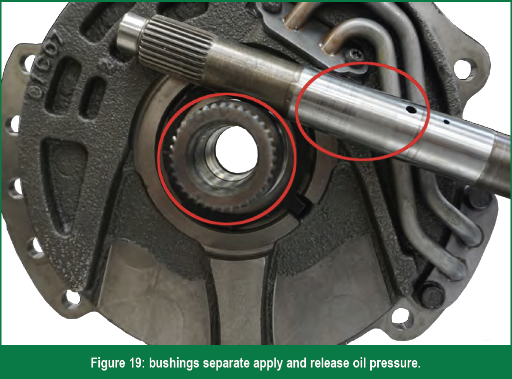 Worn Bushings – bushings, such as a stator support bushing on many transmissions, separate the apply and release oil circuits (figure 19). If a bushing is excessively worn, apply oil can sneak in the release circuit and cause TCC apply issues. Visually inspect the bushing and check for side-to-side clearance with the shaft installed. Use quality bushings and make sure you inspect the replacement bushing for fit as well.
Damaged seals – Seals on the input shaft, pump, and in the torque converter keep apply and release oil separate (figure 20). A damaged or shrunk seal could cause apply and release oil pressure to cross leak. Some manufacturers insist that you install the converter while the transmission is vertical. This might be necessary to ensure that the internal seal within the converter is not offset, which could possibly get nicked or damaged by the input shaft if the converter is installed into a horizontally positioned transmission.
Hydraulic Control:
TCC Valves – Let’s give the reman torque converter a chance! Worn out valves or valve bores could prevent apply pressure from ever reaching the torque converter. Anodized regulator valves oscillating in aluminum valve bodies might eventually lead to excessive bore wear. You can do a visual inspection with a light, a wiggle test, but a vacuum test is the gold standard for determining bore wear.
 Pressure Regulator Valves – It’s not just about the TCC regulator! Make sure line pressure is within spec. Many pressure regulator valves/bores that are worn will cause high and erratic line pressure, which is hard on pump gears, slides, as well as the converter. Pressure regulator valves feed the torque converter with release oil, so it’s important to verify main line pressure regulator valve circuit integrity. You can do this by visual inspection as well as with a vacuum check.
Solenoid Feed Valves – While reviewing a typical hydraulic schematic, you’ll notice that solenoids that have direct control over clutch and TCC pressure are fed with a regulated pressure often termed as solenoid feed, modulator, or actuator feed limit. Bob really stressed the importance of solenoid feed throughout the lecture. Converter control (as well as shift control) is very dependent on proper pressures and it all starts with line pressure and solenoid feed pressure. If the solenoid feed pressure is incorrect, either too high or too low, so will the TCC apply pressure.
Electrical Control:
Solenoid operation – correct solenoid operation is so critical on modern transmissions. The control module pulse width modulates (PWM) a current to the solenoid at a specific frequency. The solenoid expects a precise amount of inlet pressure in order to generate a precise amount of output pressure. As mentioned previously, the solenoid feed is critical, because the TCM cannot precisely control pressure if the solenoid is not feed the correct pressure. Solenoids can also fail mechanically or become sticky. Ruling out a solenoid is tricky on some units. If possible, you’re best-off substituting the solenoid with a known good solenoid. Seeing as that’s not always possible, you can usually perform the basic amperage test, resistance test, and maybe toggle it with air pressure and a battery pack. For some solenoids, such as the ZF solenoids, you can vacuum test them to ensure that when they are closed, they’re making a good seal (figure 21).  Realize that just because a solenoid opens and closes on the bench, it could still be faulty and not control pressure properly under operating conditions. Refer to the January/February 2021 issue of Gears for a good article on solenoid control from Garrett Herning entitled “Using the Right Frequency.”
Conclusion:
As transmission rebuilders, we must ensure the valve body, pump, fluid circuits, computer control, and solenoid operation are in good shape. The converter builders need to ensure that their rebuild has proper seals/bearings/ bushings, friction lining, internal clearances, and the components have minimal runout. Managers and sales staff need to educate their customers that there are some converters that simply are inadequate from the start, which really requires the torque converter be upgraded with tougher pistons, damper assemblies, and covers like what’s shown in figure 22. This holds true for stock vehicles that are used in a heavyduty fashion, like work trucks, and it’s also true for the performance customers that are tuning their trucks or racing their cars. If everyone is on the same page and if all the stars are in alignment, the table will be set for a successful overhaul and a happy customer!


