You’ve just completed the fast learn on an 8L90 followed by the adaptive drive relearn, finally getting the shifts buttery smooth and the downshifts nearly invisible. You’re not only proud of it, but you’re almost excited to see your customers’ reaction to the job. You pull into the shop, check for leaks and fluid level, and declare the job complete. The truck is then backed out and parked up front awaiting its owner, while the crew goes to lunch. When we returned to work, we contacted the truck owner to let him know the job was done and ready for pickup. The customer says he’ll pick it up in the morning. When the truck starts to bring it back into the shop for the night, it immediately has a hard drive engagement. It wasn’t this way a few hours ago. It’s the opposite of good. What happened? The Fast Learn, the adaptive test drive, the smooth shifts. To complicate matters further, the customer will be in tomorrow morning to pick up. The call to the customer to reluctantly inform him there’s an issue and the truck won’t be ready first thing in the morning went as well as one could expect. But the deed was done, and next is to get the adapts relearned once again.
The next morning, the entire relearn process is repeated, from fast learning to drive adaptation. And once again it’s smooth, and the downshifts are unnoticeable. Bitten once before and not anxious to repeat the previous day’s event, the truck is parked for a while and rechecked. Sure enough, just like before, the adaptation was gone. Was it a bad TCM? Was it a missing calibration? Did someone replace the valve body and not update the PUN? Lots of questions but few answers. The answer lies in understanding that computers operate in a specific way: they compute, analyze, and record in very specific patterns.
The Self-Test
Computers, no matter where they are or what their job is, work similarly. They perform a self-test of the processor and memory, test attached circuits, and then load and run an operating system. The operating system reviews the self-test results, and if there are no issues, it goes about its routine day. On power down, the operating system initiates a transfer of information stored in active memory to more permanent memory. The terms are volatile, meaning the memory’s contents are kept alive by constant voltage flowing through the memory chips, and non-volatile, meaning the information remains when power is turned off. In volatile memory, the 1s and 0s contained in the memory chips would very quickly fade away when power is removed. Nonvolatile memory, by contrast, retains that information. Think of this as a thumb drive. You can save a file, put it in your pocket, and days, weeks, or even months later you can pull it out and access those saved files.
On your desktop PC, the self-test occurs at power-up; it’s called POST (Power-On Self-Test). On older computers, we used to watch the memory test count from 0 to the RAM capacity and then hear that single BEEP, signifying the POST was complete. Modern PCs do the same procedure, but they test faster, and the tests aren’t displayed; instead, a manufacturer’s graphic appears. As I said, once the POST is done, the operating system loads next, and if you’ve sat in front of a Windows PC, you’ve no doubt noticed there’s a bit of a wait before the computer is ready to use. And that wait won’t work in the automotive world. Waiting for glow plugs to cycle is about the public’s tolerance level. We want to get in, turn on the engine, and go in about as much time as it takes to read this sentence.
Computers in Cars
This means the POST (power-on self-test) must be changed or eliminated. Elimination would bring severe reliability risks. You can’t simply skip testing the hardware that will run the engine, transmission, ABS, and SRS (airbags). Liability is too great. That leaves us with changing the self-test. The change moved it from the power-on procedure to the power-off procedure. This is known as the Power- Off Self-Test (POST), but that could be confusing as it’s the same acronym as the power-on test. So, Key-Off Self- Test (KOST) is more commonly used to avoid that confusion. Newer, faster computers perform both an abbreviated POST and a more thorough KOST.
Now, how does that shutdown process work? When the ignition key is turned off, either constant battery voltage is present to the module or a timed voltage is provided, depending on the model. When the module gets that ignition-off signal, it will perform:
1. Actuator Calibration & Sweeps:
- Electronic Throttle Body (ETC): Drives the throttle plate through a full sweep to find the mechanical stops, test return spring tension, and re-zero the Throttle Position Sensor (TPS).
- Idle Air Control (IAC / Stepper Motors: Parks stepper motors at a known starting position for the next cold start.
- Variable Valve Timing (VVT) / Turbo VGT Actuators: Sweeps vanes or phasers back to their default base position.
- Transmission Valve Bodies / Shift Solenoids: Performs quick circuit continuity checks and parks adaptive pressure logic.
2. NVM / EEPROM
Data Storage:
- Writes active learned adaptive values (fuel trim tables, transmission clutch volume indexes, sensor offsets) from volatile RAM to non-volatile memory (EEPROM/Flash).
- Commits pending or freeze-frame Diagnostic Trouble Codes (DTCs) to permanent memory.
3. Circuit & Sensor Validation:
- Checks for shorted or open output drivers (FETs/H-bridges) as load capacitance collapses.
- Validates low-voltage reference circuits before internal voltage regulators shut down.
That’s quite a lot of work to do after the ignition is turned off. Luckily for us, though, the computers run very fast and complete these tests and processes in seconds. You’ll note in step 2 the very important step of moving learned adaptive values from RAM (volatile memory) and saving them to non-volatile memory. Look back at the 8L90, which forgets all the adaptive values it learned after ignition shutdown. Failure to write those values to non-volatile memory certainly helps explain what is happening. But we can’t go pointing fingers at any part yet. First, we must do some testing.
What would cause a failure to move the adaptive values to permanent memory? It could be an internal fault of the memory itself. It could also be a loss of voltage to the module, preventing the KOST from operating. In some cases, this could result in a DTC, a failed circuit test, or a failed memory test. In some modules, no codes will be set.
Where do we start?
As with all electrical faults and testing, your best first step is to find the appropriate wire diagrams. Also locate a connector view, if available. With the wire diagram, we need to locate the module ground and the power inputs. Some modules may have 1, 2, 3, or more, depending on the design. We’ll stay with our 8L90 example and use that one. Every computer has a signal to turn on. Most have a power circuit controlled by the ignition switch on older models or by a gateway computer. For many vehicles, this was a BCM, but it could also be the Instrument Cluster (IC). Regardless of the method, a signal tells that module to wake up and get to work. If you trace the power inputs back to their source, you’ll find information on the schematic that tells you whether it’s battery or switched power. The easiest indication of a switched circuit is when the words “Hot in Run/Start” are used next to the circuit.
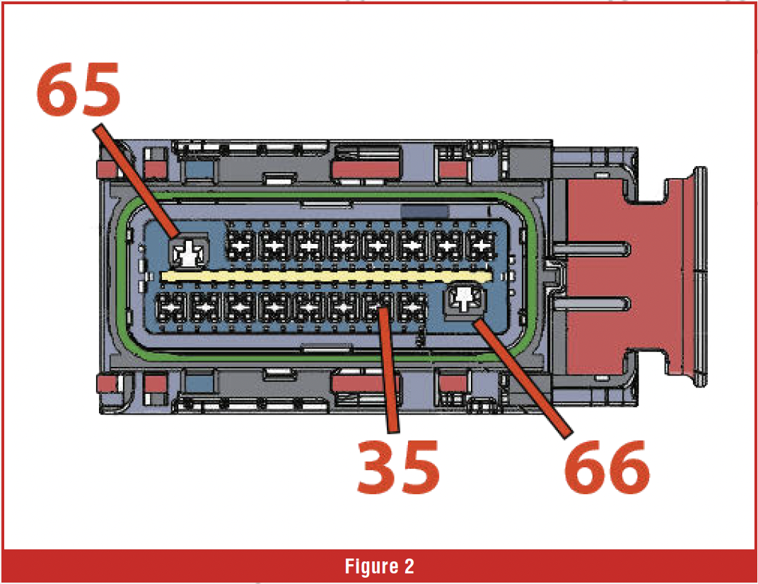
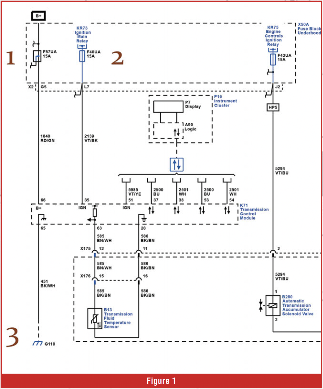 In Figure 1, circuit 1 is the switched power. Hot when the ignition is in run or start. To test this circuit, set a DMM to DC volts and measure battery voltage to establish a baseline. If there’s a drop at the module connections, then we’ll know there is a loss somewhere and can look for that. Next, with the ignition off, back-probe into pin 35 on the TCM connector (Figure 2) and measure the voltage. 0v is what we should have. Then turn the ignition on to run; the voltage should go to battery voltage. Next, check the voltage at pin 66 with the ignition off; you should see battery voltage here too. Turn the ignition on to double-check for a significant change in voltage in the run position. A slight drop in voltage without the engine running is normal as modules wake up and draw power from the battery. Lastly, check the ground circuit at pin 65. With the ignition in the run position, leave your meter on DC volts and measure the voltage difference between pin 65 and ground. You should see 0.5V or less.
In our example vehicle, if the battery voltage at pin 66 is low or missing, the TCM may power up solely on the switched power on pin 35. It will run, learn the adaptations, and appear perfectly normal. Until the ignition is turned off and the switched power is removed. Now the TCM cannot perform its KOST procedures, and all learned data is lost. It’s like Deja Vu.
 On some designs, especially newer ones, a wake-up circuit is controlled not by ignition but by another module, such as the BCM or a Gateway module. Knowing how your TCM is supposed to wake up and shut down is very important. Wire schematics can show this information, and we’ll look at this design next.
The Gatekeeper
More often, we see modules turned on through another module, especially since so many vehicles are now push-to-start. In these models, you’ll find a module that controls many other modules. The role is frequently referred to as the Gateway Module, and its role is not simply to turn modules on and off, but it manages information between networks; it also performs power modding – conserving voltage by controlling which modules are to be awakened to work and which ones will remain in sleep mode until needed. The power-conservation sequence keeps a module awake long enough to perform its KOST and write its adaptation data to non-volatile memory.
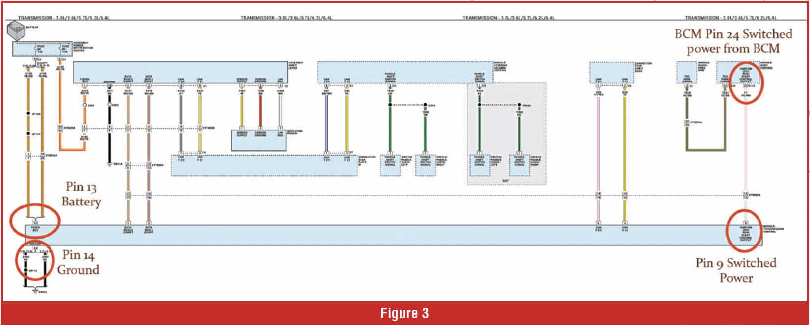 In Figure 3, you can see the circuit that turns the TCM on and off is the Pink & White wire, conveniently called IGN OFF/RUN/START CTRL OUTPUT. And that circuit is controlled by the BCM. The BCM wakes up the TCM, as well as other modules, and on shutdown it initiates the KOST and data write; then, after a predetermined time, it cuts power to the Pink & White circuit to force the TCM to shut down. Testing is like the earlier-discussed Silverado: check battery voltage at pin 13, ground at pin 14, and switched power at pin 9 at the TCM connector.
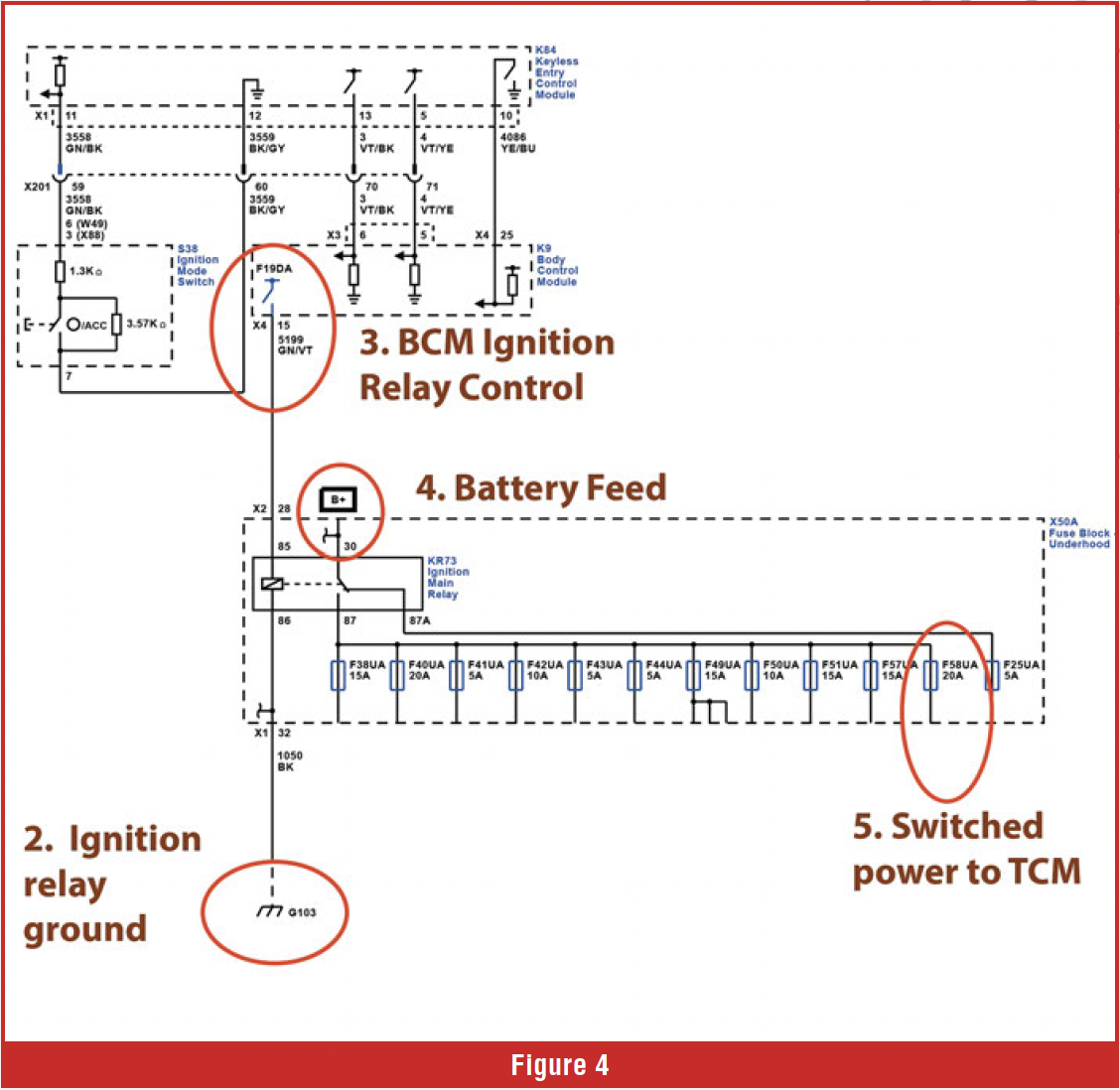
Figure 4 shows a 2020 Chevrolet Traverse that uses the BCM to turn on multiple modules at once. At circuit 1, battery power follows the circuit to the Ignition Main Relay. 2 is the ground to the coil side of the Ignition Main Relay. 3 is the BCM, which, once it detects the ignition has been turned to Run or Start, provides voltage to the coil side of the Ignition Main Relay. This causes the contacts to close, and voltage from point 1 can then flow through the circuit into many modules, including the ECM, TCM, Instrument cluster, FPCM, Serial Data Gateway module, and many others. Pretty important function with that single circuit. When the ignition switch is turned off, the BCM powers down the Ignition Main Relay control circuit after a specified time. About 17-20 seconds in most cases. This should provide sufficient time for modules to perform KOST and write their adapts.
 But sometimes that power is cut short before a complete shutdown sequence can be performed. This was a problem with some 9T applications in which the BCM cut power before the KOST could complete. In those cases, they often set a P0947 Shift Solenoid Valve 1 Stuck On at the next start-up. The cause wasn’t the solenoid, but an incomplete KOST and no record of those test results written to memory. Flashing the BCM with an updated program fixed this.
The phenomenon of premature power loss to a module is nothing new. Ever since computers were put onto vehicles, this has been an issue that has come up from time to time. Back in the olden days of computer controls, there were no adaptation tables to save; however, fault codes were saved to permanent memory at shutdown. If power was lost, then when scanned later there would be no DTC’s present. This was frustrating, to say the least, as the customer was adamant that the Check Engine Light was on but went off the next trip. Faulty wiring, failed relays, or loose connections were the common causes.
When all your testing shows good voltages and grounds, what else could cause no adaptation retention? Simply put, if the problem isn’t outside the box, it must be inside. Internal hardware failure, memory module faults, or corrupted programming could be the cause. Search TSBs for possible known module concerns. If none are found, try reprogramming the module first; if that’s not possible or unsuccessful, you’ll need to replace the module. Follow this with programming, module configuration, and then the entire adaptation process again. These tests can be time-consuming, but assuming a bad module and replacing it could leave you with a shiny new TCM that does the same thing as the original.
When you look at the problem, the cause is sometimes simple, but not understanding how a component works can turn a simple problem into a near-unsolvable conundrum. Once we understand how something works, then life gets easier.