Whether you love or hate it, Start-Stop systems are another technology that we have to address during transmission rebuild or repair. And when the system is not working correctly, you may be presented with a customer who very much dislikes the restart thump and bang into life at the light. In this article, we’ll cover all the current GM models that use the Auxiliary Fluid Accumulator as well as those that utilize an Auxiliary Fluid Pump. Either of these designs may be similar to those used by other manufacturers, but the operation and principles remain the same.
Most manufacturers use either an auxiliary fluid pump motor, which maintains pressure and volume as long as the pump has power, or an accumulator system that stores fluid under pressure and uses a limited volume of fluid. For most GM applications, the Fluid Accumulator design is used. It has the advantages of reduced complexity, ease of integration with existing transmission designs, and lower build cost.
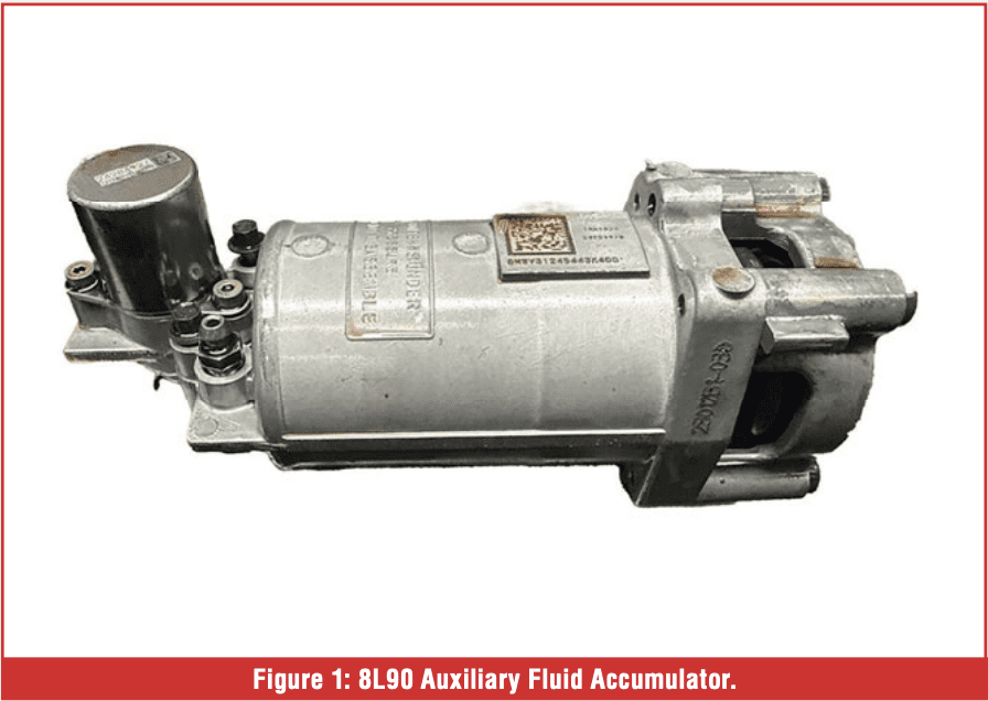
The accumulator system (Figure 1) is simply a tube containing a piston, spring, and a solenoid that controls fluid flow. When the engine is running, line pressure is syphoned off into the accumulator, compressing the accumulator spring (Figure 2).
![]()
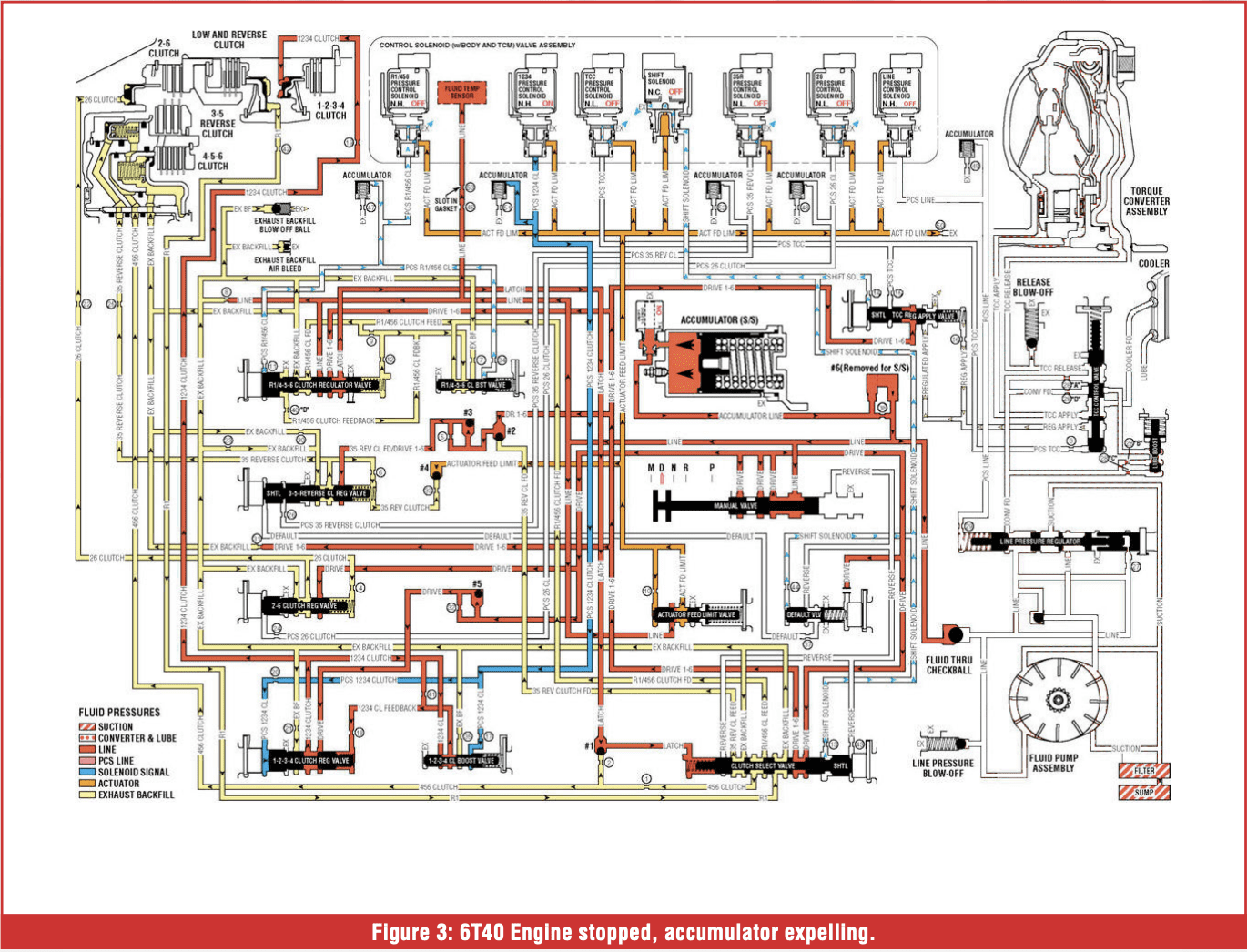
 When the Auto-Stop mode is activated, and the engine is shut down, several actions will occur simultaneously: the primary pump will stop producing pressure, and the Auxiliary Accumulator Solenoid will close to control the flow of fluid back into the transmission. Now, line pressure is no longer coming from the pump but instead from the auxiliary accumulator. The accumulator spring will now expand, moving the piston within and pushing the stored fluid back out through the solenoid into the line passage. When this pressure enters the line pressure passage, it will seat the Start/Stop check ball, preventing fluid from feeding back into the pump and regulator system. The stored pressure will also feed to the necessary clutches to maintain 1st gear apply. The available pressure is low; only enough is needed to keep the clutches applied and prevent air accumulation. For some transmissions that only require a single clutch to remain applied, others require 3 or 4 (Figure 3).
 On normal restart of the engine, the main fluid pump will again produce pressure and unseat the Start/Stop check ball, allowing pressure from the pump to flow into the line pressure passage, and once again fill the auxiliary fluid accumulator, as well as back through the clutch control and/or regulator valve, then into the already applied clutch.
With the engine off, all electrical power is supplied by the vehicle battery, and as the battery’s state of charge drops, a command to restart the engine is sent.
The accumulator itself has a limited amount of fluid, and the rate of usage provides only a few minutes of usable pressure. As the engine’s off time approaches the estimated end of fluid availability, the PCM will restart the engine, refilling the auxiliary accumulator.
When it turns mean
When there is no fluid pressure from the auxiliary accumulator, the engine restarts with a very noticeable bump or lurch. What has happened is that one or more clutches have released, and on restart, the main pump jumps back into action, with high line pressure racing through the passages at full volume and force, applying the clutches very aggressively. I say high line pressure because, until that oil reaches and reacts with the pressure regulator to reduce pressure, it will exert several hundred pounds of force.
In older transmissions, the manual valve controls the forward or input clutch feed, but in modern 6-, 8-, 9-, or 10-speed transmissions, 1st gear is engaged differently. Whether it is a park-by-wire system or a manual valve, clutch engagement is controlled by modulating a clutch control solenoid. It bleeds pressure in slowly at first, then ramps up to full apply to provide a smooth engagement. When the engine restarts from stop mode, the clutch control solenoid is already in full apply position. This means no cushion, no controlled clutch feed, but instead full apply right NOW! At this point, your customer, whose knowledge of vehicles may be very limited, can easily recognize that this is not right. As well as the TCM, it will be a cause for setting DTC P171D Aux Accumulator System Performance.

Let’s take a moment and look at P171D.
Conditions for setting P171D are: Ignition on voltage is greater than 9V. Engine-off time must be longer than 1 second. Engine speed must be less than 5 RPM during the auto-start or auto-stop event. The transmission temperature must be between 32° – 230°F (0°-110°C)
Conditions for setting P171D:
- Turbine speed is greater than the predefined threshold. Actions taken when P171D sets:
- Auto-start/Auto-stop is disabled.
- Line pressure command is maximum.
- Transmission adaptive pressure control is disabled, and current adapt values frozen.
When we look at the set conditions, there is no magic RPM. This value varies based on vehicle and engine size. Typically, it’s around 50 RPM. If the TCM sees an input RPM of 50 RPM or higher, it will set P171D.
If it only resulted in disabling start/stop, I believe most people would be content to leave it ‘broke’, but the other 2 actions make this a problem that has to be dealt with. Maximum line pressure will give us rm engagements and upshifts, but some downshifts will be bumpy. Unable to adjust adaptive pressures means it won’t try to learn its way to be smoother. It’s going to be hard shifts only.
What causes the loss of accumulator pressure
On a new job with the DTC P171D and the engagement bump, there are several areas to look at. First, the auxiliary accumulator is equipped with a solenoid that provides control feedback to the line system.
When the solenoid is open, it allows line pressure to fill the accumulator, and when the system is in stop mode, it closes to provide an orifice feed back into the transmission. A fault here can be a solenoid that doesn’t close, allowing fluid to exit the accumulator at a much faster rate than expected. A solenoid that doesn’t open may prevent accumulator fill as the orifice size reduces volume and pressure. The auxiliary accumulator may end up empty or, at best, partially filled. A leak of the accumulator piston or a worn bore may cause leakage past the piston. These accumulator bodies have exhaust ports on the spring side of the accumulator, so any internal leakage should be visible as fluid venting from the accumulator.
The next cause of accumulator pressure loss is leakage from the clutch drum, piston, or sealing ring. A leaking 1-2-3-4 clutch piston on a 6T45 may bleed enough pressure to allow clutch release. If pressure at the piston is under 25 psi, it may not overcome the return spring pressure. In the case of the rotating drums on the 8L or 10L series, sealing ring leakage or drum wear can again leak enough pressure to allow clutch release.
- The more gears a transmission has, the more components are needed in the stop mode.
- The 6T45 has to keep just one clutch applied (1-2-3-4 clutch).
- The 8T and 9T transmissions also have a single clutch applied (1-2-3-4- 5-6 clutch).
- The 8L models you need to keep 3 clutches applied (1-3-5-6-7, 1-2-7-8-R & 1-2-3-4-5-R clutch).
- The 10L models must keep 4 clutch packs applied (1-3-5-6-7-8-9, 1-2-3-4- 6-7-8-10-R, 1-2-8-9-10-R & 1-2-3-4- 5-6-R)
Fluid volume demand is low with front-wheel-drive transmissions but much greater with Rear Wheel Drive transmissions. Leakage, even slight leakage, can be accumulative and bleed out that precious limited aux accumulator pressure faster than projected. There may be times when everything appears serviceable, with a slight leak past the rings or between the case and piston housing. Individually, these leaks won’t affect operation, but in stop mode, 2 or 3 leaks combined will hemorrhage off that aux accumulator pressure very quickly.
How about those worn valve bodies?
Valve body wear can also cause hard engagement as valve and solenoid dampener wear create additional leak points. We already know how worn solenoid dampeners can affect shifts, and when in stop mode, they rob solenoid pressure that keeps the clutch control valve stroked into the applied position (Figure 4).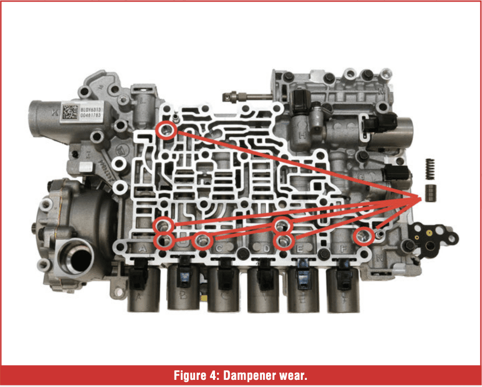
If the control valve has fully or partially de-stroked, then clutch feed may be cut off, allowing clutch release. Then, on startup, the pressure is restored; the clutch pressure control solenoid is fully applied, the clutch control valve snaps open, and the clutch is aggressively applied. Depending on which clutch was released, the aggressive apply may be mild if the input clutch is released, or severe if one of the brake clutches is released. Getting that mass of gears and drums spinning for the brake clutch can cause a very noticeable jolt.
Self-inflicted problems.
If this problem occurs after a rebuild or valve body service, we may have caused it.
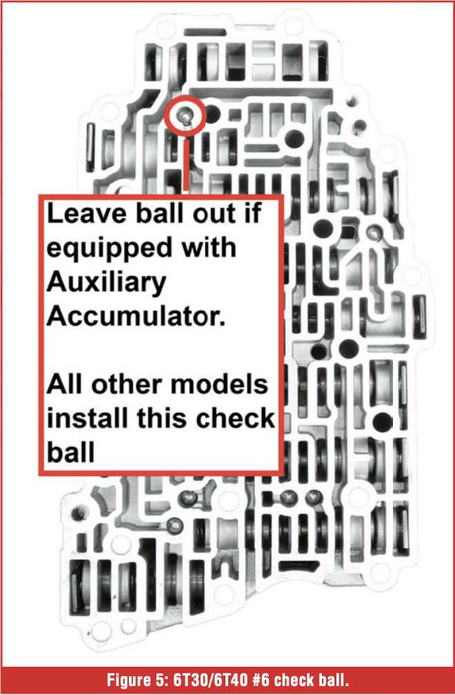
6T35/6T45 check balls (Figure 5). Non-start/stop models take 6, while start/stop models take 5. The placement of the #6 check ball may result in slow auxiliary accumulator feed.
 8T/9T transmissions. An errant placed check ball into what appears to be a check ball pocket can block the auxiliary accumulator feed (Figures 6 and 7). This can be confusing because on older models with park-by-cable systems, a check ball is present very near the auxiliary feed passage. Muscle memory may have you placing a check ball where none existed.
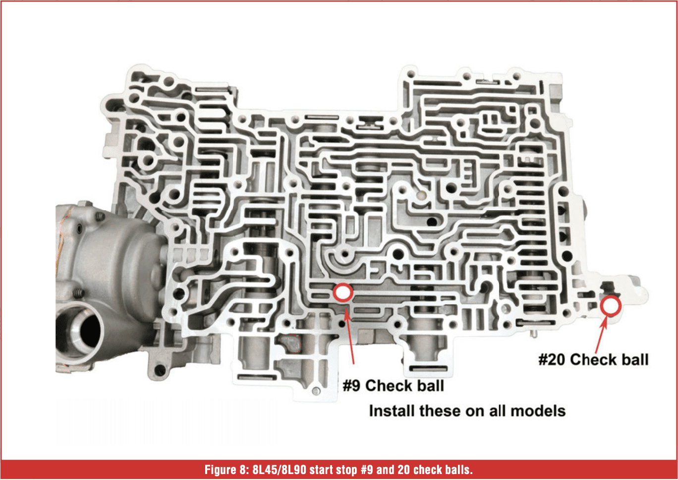
8L45/8L90 models. Check that balls #9 and 20 are required for start/stop models but are often omitted on nonstart/stop models (Figure 8). If #9 is left out, the auxiliary accumulator pressure can feed back through the pump, the pressure regulator, and the converter feed. This can cause accelerated pressure loss. If #20 is left out, line pressure will be fed back to the auxiliary accumulator solenoid. Higher line pressures under load may affect solenoid function. With #20 present, line pressure is routed through a check valve that allows accumulator fill when under line pressure and blocks release of pressure when in stop mode.
 In the GM documentation, there is a note that check balls #9 and #20 are optional on non-start/stop models. Installing those check balls on a non-start stop valve body will not affect operation in any way. The separator plate passages will determine whether a ball is needed. So, to be safe on any Gen 1 rebuild, install both check balls. On the Gen 2, #20 is optional, and # 9 is now required, although it would still serve the same function as the Gen 1, by blocking auxiliary fluid flow to the converter and cooler system. Again, installing #20 in every model will prevent accidental faults after rebuild.
It should also be noted that when replacing an 8L45/8L90 valve body, you must ensure the replacement matches your application. The non-start/stop valve body will not fill the accumulator, and you will have no pressure from it. Alternatively, installing a start/stop valve body on a non-start/stop application will give you no movement or slipping right out of the gate, as the aux accumulator feed exhausts line pressure back into the pan.
What if the Auxiliary Accumulator is leaking/faulty?
There are no serviceable parts on the accumulator assembly, and don’t let curiosity convince you to take one apart. The spring inside is compressed even when no fluid is stored. There is a lot of potential energy there, and it has great potential to cause injury or damage to surrounding objects. If there is leakage, or suspected blockage, or even spring breakage, you must replace the accumulator assembly.
Removal, care, and replacement
If the Auxiliary Accumulator assembly is not leaking and there are no prior complaints or codes related to its performance (P171D), once the assembly is removed, place it out of the way and keep it oriented to prevent fluid from draining out. Try to minimize the risk of air entering the accumulator.
If replacement is necessary, then pre-filling the accumulator on the bench before installation will ensure full capacity once charged. Filling through the feed port and opening the bleeder valve will purge most of the air from within. 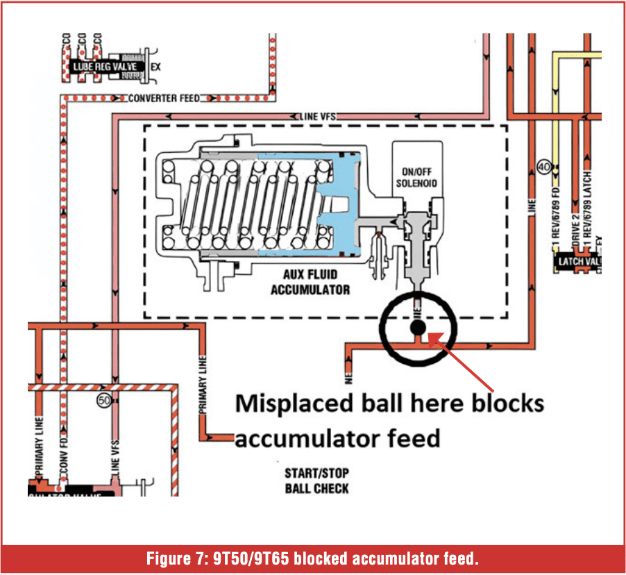 If the transmission has an external accumulator and is reluctant to fill, it is possible to bleed on top of the transmission, but be prepared to handle the fluid leak at that location. Installing a rubber line approximately 3 feet long over the bleeder will allow air and fluid to exit without puddling on top of the transmission. With the hose in place, start the engine and open the bleeder valve slightly. It should start to flow ATF out through the hose and into your waiting container. Once the flow is steady, close the bleeder and top off the transmission fluid level.
What about Auxiliary fluid pump designs?
On those models that use an electric pump to provide clutch apply pressure, things are slightly different. The auto-stop time can be longer because with a pump, there is no limitation on usable pressure. Instead, restarts will be triggered by brake release, low system voltage, or a fault in the pump motor circuitry. The output of the Auxiliary fluid pump is still regulated at a pressure lower than engine running pressures, so leakage problems can still cause a clutch release. When input RPM is detected on auto-start with the aux transmission fluid pump models, the code that can be set is now P2797 Auxiliary Transmission Fluid Pump Performance.
 In addition to the previously discussed internal leakage concerns or wear as causes of the code setting, there may also be a pump restriction, such as a restricted filter or a weak pump.
For all GM models, whether they are auxiliary pump or accumulator designs, verification of auxiliary pressure can be done with the trusty old pressure gauge. If we watch line pressure as the engine stops, the amount of pressure present and the rate of decrease are visually evident. Keeping the brake pedal applied until restart is initiated for the system voltage, we can see if the pressure runs out before the restart timer. If this is the case, then the restart jolt should be present. Observing the rate of loss can indicate potential areas, such as ring leakage, which will lose more pressure than, say, a solenoid dampener or valve wear.
As stated at the beginning of this article, other manufacturers use both pumps and accumulators for their start/stop systems, and, while the designs differ in some cases, the areas of concern are the same. Leakage at the clutch, leakage in the valve body, pump, or accumulator performance, or misassembly of valve body components or mismatched parts.
That aggressive, neutral drop on restart can be surprising and may cause your customer to come in, or worse, return after rebuild, with a very foul mood. Knowing these potential leak areas can get you zeroed in on correcting this problem and returning the vehicle back to your customer in short order. And a happy customer is your best form of advertisement.