Technicians spend a lot of time learning how sensors, solenoids, actuators, and circuits work. Technicians also spend a lot of time learning how new tools work and the best way to test all the various components on a vehicle. One thing technicians have not spent much time learning is how a computer works. The computer has always been this mysterious box that everyone is afraid of. In the next few articles, we will uncover how a computer works and some of its internal failures. Electronics have changed everything in modern vehicles; no longer does the driver need a manual switch to turn on a circuit; the computer can take care of that task. Automatic, computer-controlled features allow the computer to handle lighting and heating demands. Computers are so advanced now that they can drive the vehicle with little or no input from the driver.
Diodes, capacitors, and transistors are three things the computer uses to accomplish its task. Transistors can act as switches, turning circuits on and off, or as amplifiers. Transistors can also be used to form logic gates and memory cells. Transistors are used in series or parallel to perform Boolean operations, while memory cells combine transistors with capacitors to store binary states or use cross-coupled transistors to latch data. Boolean operations are the basic logical functions that operate on binary values. The two binary values are 0 and 1. More on Boolean operations in the next article.

Semiconductors make transistors and diodes possible. Semiconductors are made primarily of silicon and are the brains and memory of modern computers, enabling microprocessors and memory chips to process information using millions of microscopic transistors. Let’s start with the diode, a semiconductor device that allows current to flow in one direction and blocks it in the other. A forward-base diode lowers its resistance in the forward-bias direction when a current is applied. When a current with a reverse bias is applied, the diode increases its resistance, stopping the flow of current in that direction. Diodes and transistors are similar in the way that they are made, both are semiconductors, and both are solid-state devices with no moving parts. To understand how transistors and diodes work, we must visit the subatomic world. Atoms are made up of Protons, Neutrons, and Electrons. The nucleus of the atom contains Protons with a positive charge and Neutrons with a negative charge. The Electrons with a negative charge orbit around the nucleus. Without getting too scientific or going into deep detail, the semiconductor is not a conductor; it is an insulator, so it must be doped to allow current flow. The doping process forms what is called a P-N junction.
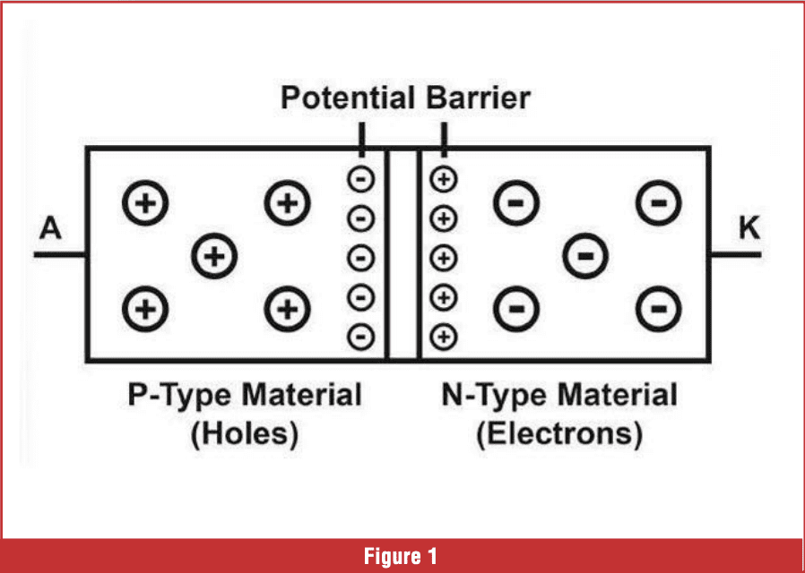
The P-Type material is doped with Indium, Gallium, Aluminum, and Boron, among others. The P-Type creates a structure that is deficient of electrons; there are holes in the material. N-Type material may be doped with phosphorus and arsenic and have an excess of electrons. The area between the P-Type material and the N-Type material is known as the depletion area. The P-Type material has holes, and the N-Type material has excess electrons, so the extra electrons in the N-Type material want to migrate to the P-Type material and ll the holes. The depletion region forms a potential barrier that prevents the natural migration of electrons. There are no free charge carriers in the depletion area (Figure 1).
 If a charge is applied to the depletion area, it will supply charge carriers into this area, allowing the diode to conduct current from the N-Type material to the P-Type material. This is considered the conductive or on state of the diode. If the power supply is reversed, it will allow the depletion area to widen, stopping the flow of current. Testing a diode requires identifying the anode side and the cathode side of the diode. In a forward-bias diode, the anode is the positive side, and the side with the stripe is the cathode, which is the negative side. Select the diode test in the meter to boost the applied voltage.
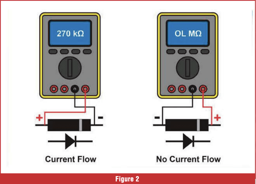 Silicon diodes require approximately 0.6 volts to turn on, and Germanium diodes require approximately 0.3 volts to turn on. Connect the red lead to the anode and the black lead to the cathode. The diode should allow current in that direction. Reverse the leads, and the diode should not conduct current (Figure 2).
Another diode commonly used is the Zener diode. A Zener diode is a semiconductor that allows current to flow in both directions at a specific voltage. The Zener diode has a highly doped P-N junction, which allows it to break down and avalanche at a certain voltage. This type of diode is commonly used for voltage regulation. Zener diodes can help supply a regulated voltage (reference voltage) to a circuit or regulate the voltage cut level to an injector.
Diodes typically fail in two ways. A diode fails short, allowing current to flow in both directions. A diode also fails open, which allows no current flow. Shorted reverse-polarity diodes cause the fuse to blow immediately. Flyback diodes that fail open may remove protection from a circuit, leaving it vulnerable to voltage spikes. The voltage spikes may also cause the computer to randomly reset, which may cause an engine stall or a momentary lapse in computer operation. Open-flyback diodes can also damage computer drivers. Open diodes may allow noise to enter computer logic circuits, disrupting the computer’s ability to process data. Diodes that fail inside the alternator allow A/C voltage to enter the electrical system and interfere with any variable-reluctance-type sensors, causing noisy sensor circuits and an array of drivability problems.
Transistors are also semiconductor devices that operate and are built on the same principle as a diode. There are several types of transistors used in modern computers; one is the MOSFET, and the other is a Bipolar Junction Transistor (BJT). The BJT is a common type of transistor used in modern vehicles. The BJT is constructed with P-Type material, which has holes, and N-Type material, which has an excess of electrons, just like the diode. One difference between a diode and a transistor is that a diode has two terminals, whereas a transistor has three. The Emitter, the Collector, and the Base make up the three terminals of the BJT. The BJT can be viewed as two diodes connected in series (Figure 3).
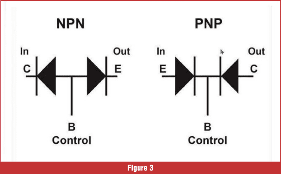 The BJT transistor comes in two types: NPN and PNP. The NPN connects two negative terminals to complete a circuit and turn on a load when a positive voltage is applied to the Base. The PNP connects two power circuits, completing the circuit to turn on a load when ground is supplied to the Base. Let’s go inside the BJT to see how this solid-state device works.
The NPN Emitter and Collector are made up of N-Type material. The Base is made up of P-Type material. There are two depletion regions that set up potential barriers. Depletion regions form at the edges of the PN junction. To activate the BJT, a voltage must be applied to the P-Type material at the base terminal. This will bias the transistor, allowing a small current to flow from the Base to the Emitter, and it will also allow the Collector to be connected to the Emitter, completing the circuit and turning the load on. Just like the diode, it takes approximately 0.7 volts to activate the Base connecting the Collector to the Emitter.  The BJT transistors can control the current flow from the Collector to the Emitter by changing the current through the Base. It takes approximately 0.7 volts to turn the Base on, but the Base is controlled by current. Low current through the Base results in lower current flow from Collector to Emitter; higher current through the Base results in higher current flow from Collector to Emitter. NPN transistors, the Collector is connected to the load, and the Emitter is connected to ground (Figure 4).
The NPN transistor can be tested using the diode test in your meter. There should be low resistance from Base to Collector and Base to Emitter. There should be high resistance from Collector to Emitter, Collector to Base, and Emitter to Base.
Next, we will discuss the PNP transistor. The Emitter and the Collector are made from P-Type material, and the Base is made from N-Type material. There are two depletion regions formed between the P-Type and N-Type material. The Emitter is connected to a voltage source, and the Collector is connected to the load. 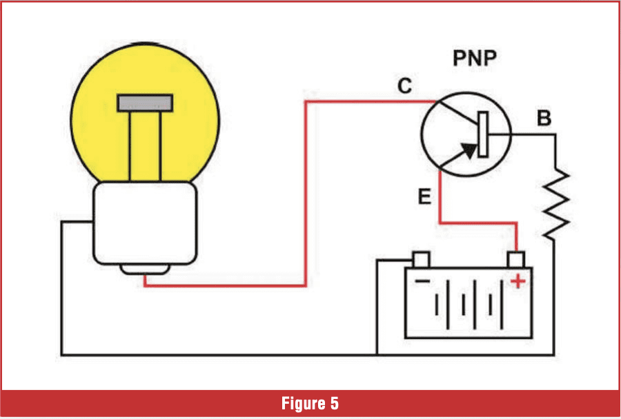 The PNP transistor is activated by supplying ground to the base; the emitter voltage must be 0.7 volts or above to bias the transistor to turn it on. When the Base is grounded, the Emitter will flow a small amount of current through the Base. The base can be controlled to adjust the current flow from the Emitter to the Collector. The greater the voltage drops through the Base, the higher the current that flows through the Base from the Emitter. The greater the current flow through the Base, the more current will flow between the Emitter and Collector (Figure 5).
The PNP transistor can be tested using the diode test in your multimeter. There should be low resistance from the emitter to the base and low resistance from the collector to the base. There should be high resistance between Emitter and Collector, and there should also be high resistance from Base to Emitter and Base to Collector.
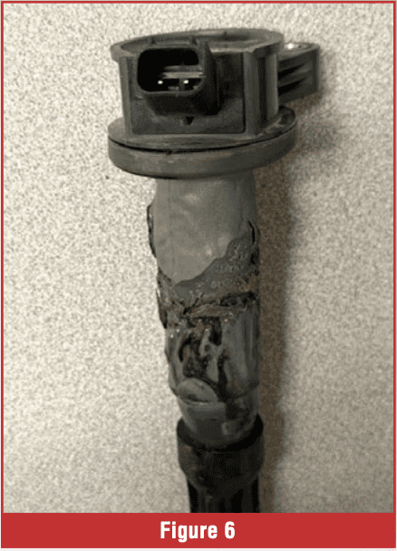 Transistors may fail from thermal overstress due to excessive power dissipation, leading to permanent damage. They can fail due to overvoltage, voltage spikes, or component shortages, resulting in excessive current. Transistors may short-circuit and stay on, causing a component to stay on. If the ignition coil transistor stays on, it can melt the ignition coil (Figure 6). If a fuel injector transistor driver stays on, it can hydrolock the cylinder. A transistor can also fail open, preventing the load from working.
Transistors are easily tested when disconnected from the circuit board, however the technician does not have access to all three terminals at the computer’s connector. The technician only has access to one terminal at the computer’s connector. The computer must be sent to a circuit board specialist to be tested properly. In the next article, we will delve into MOSFETs, capacitors, logic gates, and memory cells.
The figures use pictures courtesy of Bernie Thompson, with permission granted.
About the Author: Jerry Stewart develops technical training at AVI and teaches automotive technology at Highlands College in Montana. He bridges the gap between industry and academia, equipping students with real-world skills for careers in the transportation field.