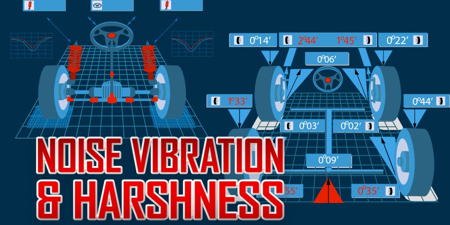
Noise, Vibration & Harshness (NVH) concerns can be very hard to diagnose without some specific knowledge and the right equipment. Customers may struggle to explain what they hear or what they feel to the service writer. It is important to identify the noise or vibration the customer is concerned with, or you may fix a noise or vibration they weren’t concerned with, while not addressing the problem they want fixed. That very thing happened to me when a customer threw me the keys and said, “my vehicle is making noise”. I test-drove the vehicle and quickly identified that the input bearing was noisy inside the manual transmission. I rebuilt the transmission, which cured the noise. The customer picked up the vehicle and drove off, but returned angry because the noise they were concerned about was still there. The customer thought the noisy bearing was normal and was not concerned about it. So let’s make sure we fix the noise or vibration the customer is concerned about.
Vibrations and noise can be heard or felt, but can they be measured? The answer is yes; they can be measured with the right equipment. If we don’t have the right equipment or don’t know how to use it, we typically guess. Guessing can be very costly when we guess wrong. In this article, we will look at vibrations. Vibration can be felt. Vibration travels through the vehicle’s suspension, steering components, driveline, and body panels. Vibrations involve physical properties of an object and conducting properties of an object.

There are two types of vibrations: forced and free. The most common type is a forced vibration. A forced vibration occurs when two connected components force each other into vibration. An example would be a bent differential pinion flange or pinion gear that vibrates and forces the vibration into the driveshaft.
 A free vibration occurs with an initial input of force and vibrates freely in the absence of any outside force affecting it. An example would be an antenna mounted on the fender vibrating after you hit a pothole. The initial force is input into the antenna from hitting the pothole, causing the antenna to vibrate. The antenna will continue to vibrate until the motion dissipates. A bent pinion flange or bent pinion gear can be measured with a dial indicator or an angle finder (Figure 1).
Vibrations all have a source; something is causing the vibration. Vibrations have a transfer path that leads to a responding component (Figure 2). An example of this could be that the front tire is the source of the vibration. The suspension is the transfer path, and the responding component is the steering wheel. The vibration can be felt in the steering wheel, yet the steering wheel is not the cause of the vibration. Most often, the technician will need to repair the source of the vibration, but sometimes the technician must repair the transfer path or responding unit as well.
![]()
 All rotating parts generate normal vibrations; these must be isolated from the passenger compartment. If bushings or mounts designed to isolate vibrations are damaged, the vibration may be felt in the passenger compartment. In the event a mount or bushing is bad, we are not trying to repair the source but the transfer path. Vibrations that are felt while driving the vehicle are typically caused by a rotating component. All rotating components create a rotating frequency.
How do we identify the offending component? We must identify the components’ operating frequency. Frequency is the number of complete turns a component makes per second. We can identify the frequency of the engine by using a scan tool to observe RPM and dividing the RPM by 60. The engine operates at a different frequency than the transmission output until the transmission enters direct drive, and the lock-up torque converter has been fully applied. The tires and axles rotate at a different frequency from the transmission or engine. Vibration frequencies are like diagnostic codes. Diagnostic codes are expressed in areas such as the 100 series for air-fuel ratio errors and the 300 series for misfires. The first number of the code tells you which system the problem is in. Vibrations are categorized by frequency. Each area operates in a different frequency range. Once we identify the offending frequency, we know what system to inspect.
 Vibrations can be measured with a device called an accelerometer (Figure 3). NVH accelerometers measure in three axes, X, Y, and Z. The X axis is fore/aft (Back & forth). The Y axis is up and down. The Z axis is side to side or lateral. If you only have one accelerometer, it can be moved from location to location to get the best results. Typically, the accelerometer is placed on the driver’s side, inside the seat rail, to begin testing with the Pico NVH single accelerometer tool. Some NVH tools have multiple accelerometers that can be placed at each corner of the vehicle or moved to a specific location. If you are using multiple accelerometers, you can compare readings to pinpoint the problem area. Vibrations are usually felt in the 0-200 hertz range.
The transmission output shaft will have the same frequency as the propshaft. The input shaft of the transmission and the output shaft of the transmission will operate at different frequencies in all gears except the direct drive gear. In a direct-drive gear, the input is locked to the output at a 1:1 ratio. In underdrive gears, the input shaft will operate at a higher frequency than the output shaft. In overdrive gears, the input shaft will operate at a lower frequency than the output shaft. The formula to determine output shaft frequency is Engine hertz divided by gear ratio. If the torque converter is fully locked up, the formula is accurate; if the converter is unlocked, the formula is slightly off.
 Axle frequency will be much lower than the transmission output shaft frequency. The differential provides a gear reduction to axles. There may be a tag on the differential or a door sticker listing the differential ratio. To determine the axle ratio, we start with the driveline’s rotation frequency in hertz. The formula to determine axle frequency is as follows. Driveline frequency divided by rear axle ratio equals axle rotation frequency.
Vibrations are measured in frequencies and classified in orders. An order simply means how many shakes per revolution. The NVH software can be configured in a multitude of orders. The common orders are .5-1.0-2.0-3.0- 4.0 but are not limited to these. Figure 4 shows common orders for tires, engines, and propshafts. You can only balance a first-order vibration.
 Vibrations are not just measured in frequency but also in amplitude. Amplitude refers to how harsh the vibration is. Vibrations operate in cycles. Each cycle starts at the midpoint, travels to an upward threshold, then back to the midpoint, and finally down to the lower threshold. The difference between the lower and upper thresholds is called the peak-to-peak amplitude (Figure 5). Severe vibrations have a higher amplitude. Minor disturbances have a lower amplitude. Vibration harshness or intensity is measured by the accelerometer in mg; in which m equals mass, and g equals acceleration due to gravity. The higher the mg reading, the more intense the vibration is.
Figure 6 is an example of a tire vibration that had a high first-order vibration. A first-order vibration can be balanced; however, if this had been any other order, it could not be balanced.  The amplitude is shown as T1, which is the first-order tire vibration. The vibration amplitude was measured at 59.8mg, which is very high. Any amplitude higher than 10mg is worth investigating. The recording reveals there are no engine or propshaft vibrations currently.
Improper driveline angles or misaligned driveline components can create a vibration. Drive line vibrations usually fall into two categories: torsional and transverse. Torsional vibrations refer to vibrations created by power pulses. The engine outputs power in pulses, which are transmitted through the drivetrain. When an engine is operating, the power pulses are minimal and not felt in the drivetrain. If the engine has a misfire or the torque converter lock-up clutch is not holding, the power pulses will be felt. Torsional vibrations may also come from u-joint angles that are not correct.  Transverse vibrations refer to vibrations created from an unbalanced driveline. A driveline may have a thicker area of metal, creating a heavy spot on the driveline. This heavy spot can be balanced using weight to offset the vibration.
Driveline vibrations typically fall under first, second, and fourth-order vibrations. First-order vibrations are caused by a bent driveline, an out-of-balance driveline, or a u-joint that is mounted off-center. Glued-in u-joints may be installed off-center slightly by the manufacturer. The manufacturer balances the shaft, and all is fine until you change the u-joints. You should check to see if the u-joint is off-center by measuring the depth of the cap (Figure 7). If the u-joint is slightly off-center, the shaft must be balanced after the u-joint has been replaced.
 It is important to remember that we can only balance first-order vibrations. We should, however, never try to balance a shaft that is bent. Second-order vibrations are caused by a worn u-joint or improper u-joint working angles (Figure 8). Fourth-order vibrations are usually caused by worn U-joints.
NVH is a deep subject, and we can only cover a few things in the short time we have in this article. Look for future articles that will explore NVH in greater depth.
About the Author: Jerry Stewart develops technical training at AVI and teaches automotive technology at Highlands College in Montana. He bridges the gap between industry and academia, equipping students with real-world skills for careers in the transportation field.