
It seems like a generational thing when we look back at transmission families of the past. GM, Ford, and Chrysler follow similar patterns for creating transmission technology that spans each era’s full torque/horsepower spectrum. Back in the day, Ford graduated from the different versions of the Cruisomatic to the C3, C4, and C6 units. More recently, we enjoyed the 4R55E, AODE, and E4OD family. We have a similar scenario with the 10R60, 10R80, and 10R140 units. This article will give you an overview of these units, their similarities, and their differences.

IN GENERAL
Ten-speed rear-wheel drive technology was a joint effort between GM and Ford engineering. Ford used the 10R80 as a blueprint for the 10R140 and the subsequent 10R60 applications (figures 1a-1b). As a result, the design of the variants fits the torque requirements of different engines more accurately. Needless to say, most of the parts inside these units are not interchangeable.
The 10R series transmission consists of four planetary gear sets, six clutch assemblies, and a valve body assembly. Four rotating clutch assemblies and two brake clutches produce ten forward ranges and one reverse gear. The valve body assembly controls gear selection through solenoids acting on valves as commanded by the Transmission Control Module (TCM). Programming in the TCM interacts with the ECM and various sensors inside the transmission to provide the correct range based on demand and driving conditions. All applications utilize a one-piece case design.
 “MUST-DO” HANDLING TIPS

The saying, ‘the apple doesn’t fall far from the tree’ applies to these units when it comes to things to be aware of when handling them. Critical items must be addressed in detail; otherwise, your best intentions for a successful repair will be met with sure failure! First, always use the correct fluid. This unit calls for Mercon ULV. It’s specially formulated for use in these units. Failure to use the correct fluid will lead to shift quality concerns and unit failure. Always ensure that the level of the fluid is correct by using the following procedure:
- Connect the diagnostic scan tool and position the vehicle on a hoist.
- Place the transmission selector in each gear position with the engine running, holding approximately 6 seconds in each range.
- Place the transmission selector in Park.
- Remove the transmission fluid fill plug and remove the transmission fluid level indicator from the plug.
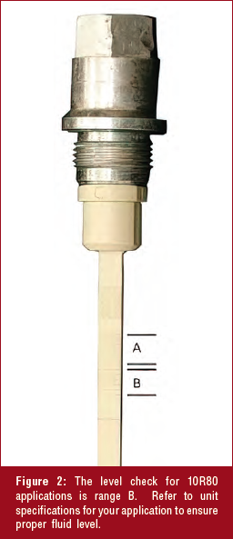
- Check the transmission fluid level using the transmission fluid level indicator.NOTE: The transmission fluid level indicator has two areas for the fluid level, A and B, as shown (figure 2). The different areas are for other vehicle models. Use the area “B” when checking the transmission fluid level. The correct transmission fluid level is at the center of the “B” area on the transmission fluid level indicator. Using the scan tool, verify the transmission fluid temperature is between 96°C – 101°C (206°F – 215°F). On the transmission fluid level indicator, the transmission fluid level must be at the center of the “B” area.
- If the transmission fluid is not at the correct level, follow the steps for adding or removing transmission fluid.
- Install the transmission fluid fill plug.
Never attempt to drive the vehicle with the level low. Complete unit failure will occur in a short period of time!

Another must-do is performing an Adaptive Learning Drive Cycle. Perform this procedure before condemning the transmission for removal if you suspect that prior repairs were performed that may have affected the transmission operation. This procedure must be performed if the transmission was rebuilt or replaced, the TCM was replaced or reprogrammed, major engine work was performed, or air/fuel management adaptive values were reset. The Adaptive Learning Drive Cycle is performed on a level road as follows:
- Record then clear DTC’s
- Drive the vehicle until the engine and transmission reach normal operating temperature.
- Accelerate from a stop with light throttle (15%), ensuring that upshifts 1st through 8th occur at engine speeds between 1300-1600 rpm.
- Continue to accelerate (may apply slightly more throttle after 7-8 upshift at 32-38 mph (51-61 km/h) until you achieve 55 mph (88 km/h) and the 8-9 and 9-10 shifts complete.
- Brake gently to a complete stop and hold the foot brake for five (5) seconds.
- Shift the transmission to Neutral. Wait 1 second.
- Shift the transmission to Reverse. Wait 2 seconds.
- Shift the transmission to Neutral. Wait 1 second.
- Shift the transmission to Drive. Wait 2 seconds.
- Repeat Steps 3 through 9 six (6) additional times.
After the final step, place the vehicle in park and cycle the ignition key off. Wait 3-5 minutes before driving to ensure enough time for the coding to be written to the module.
IT STARTED WITH THE 10R80
In 2017, Ford used the 10R80 paired with the 3.5L Ecoboost V6 in their best-selling truck, the F-150. It was versatile enough to be later placed with the 2.7L turbocharged engine through the 5.0L V8 applications. With an input torque rating of 590 ft-lbs. (800 Nm), the 10R80 covered a wide range of engine applications. The available gear ratios created a seamless driving experience for almost every conceivable throttle demand and terrain. Powertrain management programming allowed the engine to be fuel efficient while simultaneously keeping a full-power acceleration ready on command. The weight and size of the unit made it versatile for a wide range of rear-wheel-drive applications.
The model year 2020 ushered in the 10R140. This unit replaced the 6R140 for the Super Duty applications. The overall weight of the transmission assembly remained about the same despite the addition of 4 forward ratios and several other internal changes. Enhanced torque management programming allows this unit to effortlessly handle up to 1,050 ft-lbs of torque.
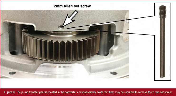
The most noticeable change over the 10R80 application is the front end of the unit. While all 10R units use an off-axis pump, the 10R140 has a unique setup for the gear drive. Depending on whether the unit is equipped with a PTO, the pump drive gear setup will differ (Figures 3 and 4). Note that these components are very heavy. Therefore, an engine hoist or equivalent to remove and install is highly recommended.
The 10R60 is the latest addition to the 10R family. With a maximum input torque rating of 443 ft-lbs (600Nm), it is specifically designed for the lowest torque output engines Ford manufactures. Introduced in the new 2021 Ford Bronco, the unit is lighter and physically smaller than the 10R80, implying better fuel efficiency.

WHAT THEY HAVE IN COMMON
The one component with the slightest variance is the valve body. The basic assembly is the same but cannot interchange between the variants. All units share the CIDAS (Casting- Integrated Direct Acting Solenoid), Pressure Control, and Torque Converter Clutch solenoids (figure 5).
While the solenoids are all position-sensitive, the OEM replacement is the same base part number for all variants.
A pump whine complaint is common. The 10R series transmissions use straight-cut transfer gears to drive an off-axis pump. As we remember from manual transmissions, straight-cut gears are known to whine. Therefore, the noise is a normal condition and does not affect the unit’s durability. Do not attempt to correct!

Shift strategy is another item shared in the 10R family. Skip-shifting is normal and dependent on throttle demand and other load factors. Not all ranges will be selected in sequence on the upshift or downshift. For example, if you take off from a stop under moderate throttle pressure, you may experience a 1-3-5-7-8-9-10 shift sequence. A similar scenario may occur on deceleration. The TCM programming algorithm is designed to work seamlessly with the engine to produce nearly unperceivable shifts while providing the correct ratio given driver demand and driving conditions.
Torque converter scheduling is designed for maximum fuel efficiency. As a result, the converter clutch apply is noticeably delayed for smaller displacement engines compared to larger high-torque engines.

Normal operating temperature is a curious subject for discussion for these units. We have spent our whole transmission career trying to find ways to keep our units cool. Our mantra is the cooler the transmission runs, the longer it will live, right? Well, that goes out the door with these units! The normal operating temperature range for the 10R applications is 195°F to 215°F (90°C to 101°C). Yes, this is the OEM specified range, so don’t correct it. Everything from the friction and steel plates to the fluid is designed to function at its optimal level when the unit reaches this range. So, on a hot Arizona day, when you are pulling a 40-foot trailer uphill to the lake, it is common to see temperatures spike as high as 230°F!
ISSUES AND PATTERNED FAILURES
These units have not logged a substantial amount of miles; however, we are beginning to see some common issues. Low mileage issues such as poor shift quality and no engagement are attributed to debris entering the valve body. Note that programming updates solve most shift quality issues.

Always check the appropriate reference material for software updates. Sticking valves and CIDAS solenoid pintels are common concerns. It is necessary to replace the valve body when CIDAS solenoids fail. Individual solenoids are not available at the time of the printing of this article.
Higher mileage units experience issues with the CIDAS solenoid retaining clips becoming loose (figure 6). It is a spring-type clip designed to keep the base of the solenoid secure in the bore. However, the clip flattens with time, allowing the solenoid to move in the bore, causing wear in the area where the solenoid sits. In addition, the movement of the solenoid causes inaccurate control of the valve, resulting in flared or binding shifts. Currently, the clips are not available and must be secured from a ‘donor’ valve body. However, the aftermarket has a solution in the works!

Issues of binding, flared shifts, and neutralizing are more common with 10R80 applications. Gear ratio codes may or may not be present. These concerns are caused by the inner sleeve of the C-D-F drum moving out of position (figure 7). A diagnosis usually results in varied shift concerns that can not be corrected using a drive relearn procedure. Changing the valve body will often make the issue worse. Replace the drum as necessary.
While the design is similar to the 10R80, the 10R60 is experiencing growing pains. An issue of harsh 6-7 shift is attributed to the A-clutch return spring snap ring popping off (figure 8). There is an updated housing assembly to correct this issue.
Keeping up with the latest technology can be a chore. Following the latest failures and fixes can be even more challenging. ATRA aims to give you the edge you need to make your job easier. After all, it is a transmission family affair!


