
No, not the nocturnal dude with the cape and fangs. We’ll be looking at the “Digital Ratio Adapter Controller” (DRAC). That’s a mouthful, so we’ll be saying DRAC from now on. Another name sometimes used in wiring schematics is “Vehicle Speed Buffer.”
It was used on most GM vans and light-duty trucks built from 1988 to 1994. Its purpose was to change the A/C signal from the speed sensor into a DC pulse signal that the computer can understand. You might be wondering why I’m covering a topic that’s so old. Hot-rodders have an interest in some of these vehicles, and the information is becoming harder to find. Not to mention, it’s just fun working on this stuff.
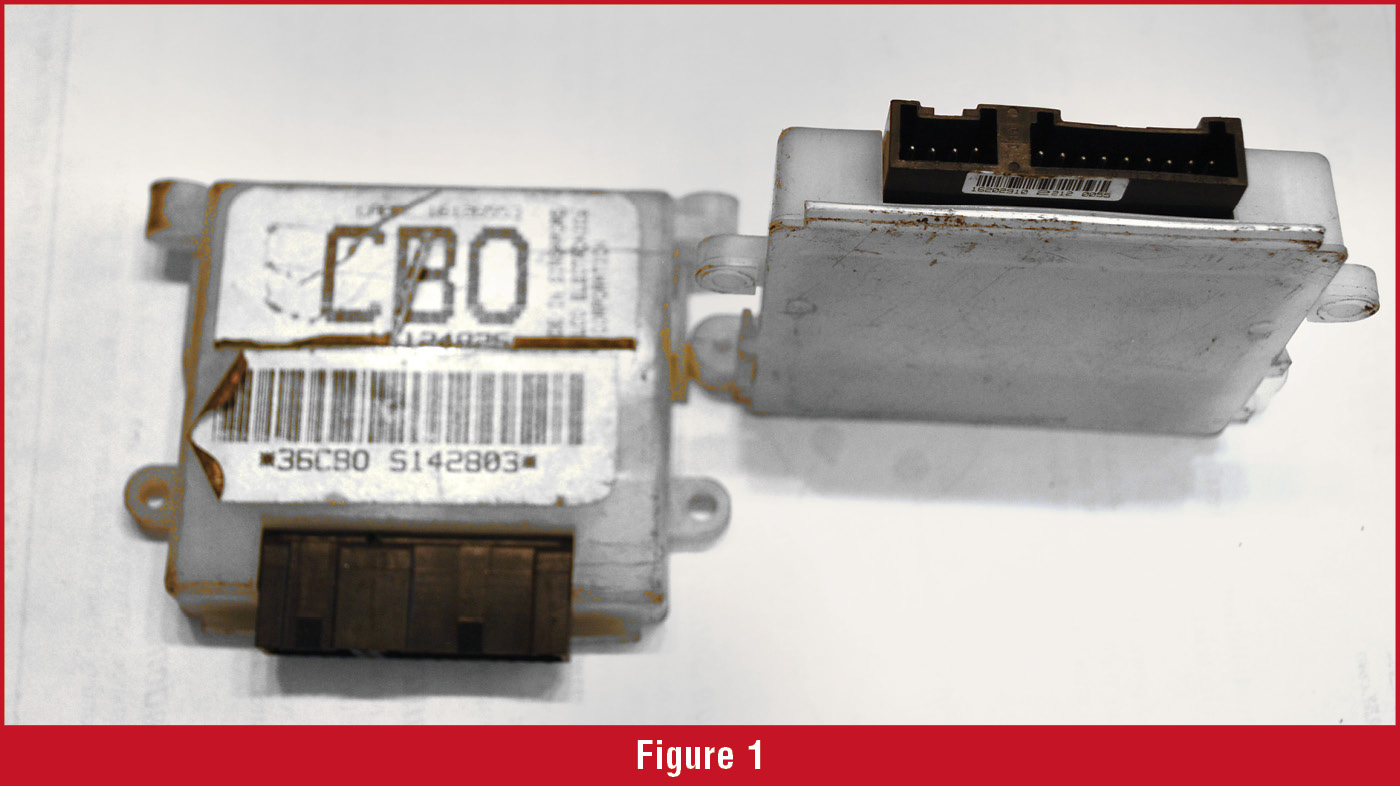
The DRAC is usually mounted on top of the PCM that is hidden behind the glove box. It’s fairly easy to access, compared to what we sometimes have to go through today. It’s located in a white plastic case. (Figure 1) Open up the case, and we see jumpers, or “strips” that define the DRAC’s calibration. These are just wire connectors from one contact to another. They’ll either have a “strip” connecting the two contacts, or they’ll be open. In the old days, you’d buy a replacement that had all of the strips connected. Then, all you did was cut the strips you didn’t need, so it looked like the old one. This’ll make more sense in a moment.
 The DRAC came in two varieties (Figure 2); one had seven strips (1992 and ‘93). The other had 14 strips (1994-on).
The DRACs prior to ‘92 are inside of the instrument cluster, and the same procedure for the ‘92 and ‘93 models will apply.
Now, you may find one of these older vehicles where the speedometer reads incorrectly because your customer turned an old truck into an off-road machine with giant tires or they’ve changed the differential to a different ratio. In these cases, you can fix these calibration problems with a calculator, a soldering iron, and a little patience. There are companies selling reprogrammed DRACs ready to go, but this is easy.
Let’s start with the math. You’ll want to calculate something called the “divide ratio.” Simply put, it equates to the number of DRAC pulses, over distance, to the speedometer. By itself, it doesn’t have much meaning, but it means everything to the speedometer, and you can figure out the divide ratio with a few simple calculations.
For the calculations, you’ll need three things. They’re listed below, and I’ve included example numbers with each one (in parentheses). They are:
- The tire circumference (90”)
- The axle ratio (3.73:1)
- The number of teeth on the speed sensor tone ring (40)
 First, let’s find the tire circumference. The most direct way is to mark the tire at the 6 o’clock position (a sharpie or piece of tape work). Make an accompanying mark on the floor. Now move the vehicle, so the tire makes one full revolution, and the tire mark is back to the 6 o’clock position. Make another mark on the floor. The distance between the two floor marks is the circumference. In our example, we’ll divide the number of inches per mile (63,360) by 90 (our example circumference). 63,360 ÷ 90 = 704. This means the tire in our example rotates 704 times per mile.
Now let’s find the axle ratio. Using the tag on the differential or the RPO code is the easy way. If you don’t have that (or if someone changed the axle ratio), then you’ll need to count the teeth and find it that way. In our example, we have a differential with a ratio of 3.73:1. So, we’ll take the ratio and multiply it by 704. 3.73 X 704 = 2,625.92. This is the drive shaft revolutions per mile (we’re almost done).
Now multiply 2,625.92 by the number of teeth on the VSS ring (we used 40 in our example). This gives us: 2,625.92 X 40 = 105,036.8. This is the number of A/C pulses produced by the VSS, per mile. Now divide that by 4,000 and you have the divide ratio: 105,036.8 ÷ 4,000 = 26.259.
There you have it. The divide ratio for our example is 26.259. Find that ratio in one of the charts (it’s in chart B, Figure 3).
 The closest divide ratio in the chart is 26.172, we’ll use that. Notice the switch settings in the chart are; off, on, off, off, on, off, on. The way to interpret this is that “on” means connected, and “off” means the circuit is open (disconnected).
If you go back to the DRAC in figure two, you’ll notice that only two of the seven strips are what we need. Snip three of them to open the circuits and solder two of them to close the circuits. If you’re handy with a soldering iron, it’ll take about 15 minutes.
But what if you have a 14- pin DRAC, like the one on the right in figure two? That’s easy. Use the same method to find the drive ratio and treat the first seven strips as you would a seven-strip DRAC. Then reverse the strip condition and continue. That is, just interpret the chart backward. In our example, it’d be: on, off, on, off, off, on, off. It’s easy. Also, notice the soldering mess someone made with the 14-strip DRAC in figure two. This likely isn’t going to work. Be careful that you don’t solder one circuit to the adjacent circuit, as it appears in the illustration.
You may not have to use this information very often, but you’ll find that when a request comes in for this type of work, you’ll be glad that you have it, and easily make a few extra bucks that day!
Good Luck!


