Vehicle speed systems have been in use for nearly 140 years, with the first application on trains. Keeping schedules working, knowing the speed of travel was as important then as it is now. By the turn of the 20th century, speedometers had begun to appear in automobiles. The need to know how fast and how far a vehicle traveled became increasingly important as more vehicles came into use. These early designs were often mechanical, featuring gears that turned a cable, which in turn activated a calibrated speedometer mechanism. This mechanism contained a magnet, a needle attached to an aluminum cup, and a gauge to indicate speed. The design was improved and remained in use for 70 years.
From Cables to Circuits
As time passed, we ditched he mechanical drive systems for electronic sensors. First optical, then fully electronic. This move became essential for electronically controlled transmissions and engines.
On these early systems, gear ratio faults were set when the PCM/TCM calculated the engine speed that the engine should be at for a commanded gear and indicated the road speed. We could see this in codes like P1870 Transmission Component slipping. It wasn’t definitive as to the fault area, but it did show the engine was running faster than it should, and you should be looking for a slip in the transmission.

As with every technology, as it develops, its use expands beyond the original intent. On today’s vehicles, we have speed sensors from the engine to the wheels, and all points in between. With so much data available, there is an increase in accuracy, verification, and redundancy. With so much overlap, the computers onboard can accurately calculate vehicle speed even when one signal is missing, unlike those old cable-driven systems. Often, the first indication of an errant speedometer was red flashing lights in your rear-view mirror. Today, we might see a Check Engine or ABS light illuminate, or even an alteration to transmission function.
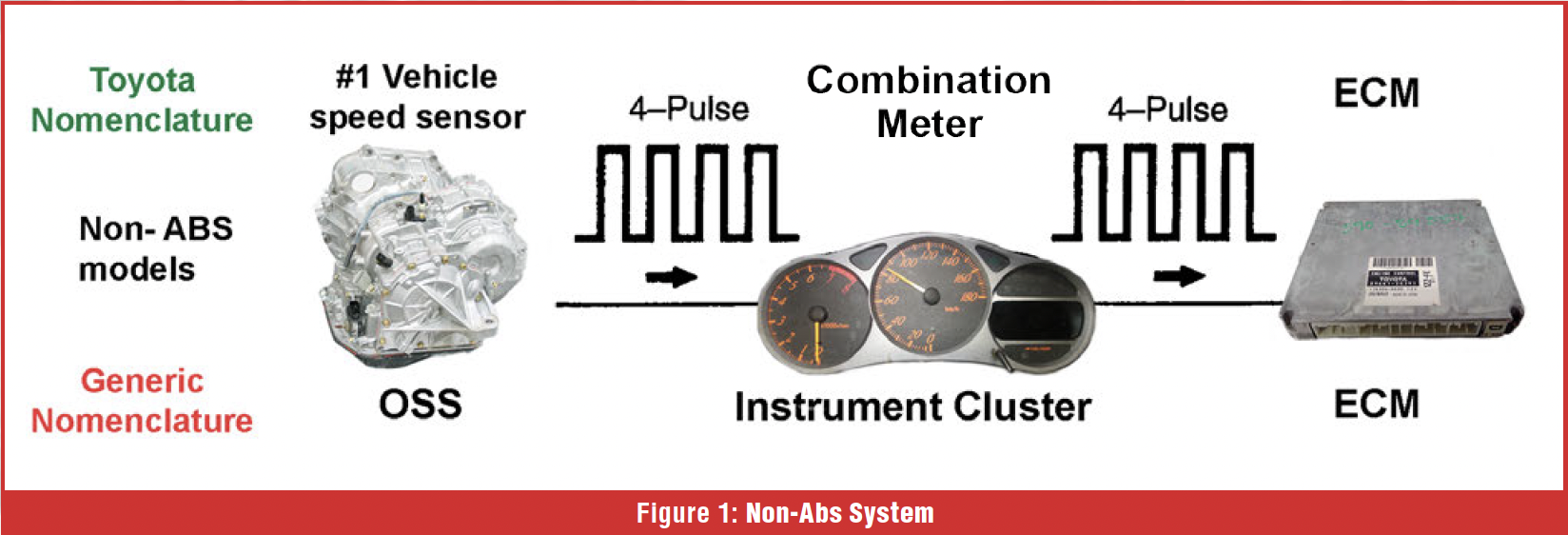
Let’s break down evolution a bit further. One of the early adopters of utilizing ABS wheel speed sensors was Toyota, using the wheel speed sensors to provide actual vehicle speed. The transmission still retained an output speed sensor. Still, instead of using that data to determine vehicle speed, it has now become the data against which the vehicle speed sensor (ABS) data is checked, as well as gear ratio monitoring. Note that on those early models, the vehicle may or may not have ABS. On those with no ABS option, the OSS on the transmission was the VSS source. (Figure 1).
Redundancy and Reality Checks
With the use of wheel speed sensors, we bring in redundancy. Instead of one sensor, we have four. And four is better than one, right? In the case of verification, it is. Manufacturers use similar verification methods in throttle control systems. The Accelerator Pedal Position Sensor is comprised of two or three potentiometers that monitor the accelerator pedal position. By having this redundancy, it can be recognized when a fault in one sensor is experienced. The use of wheel speed sensors also permits fault recognition, but there’s a catch.
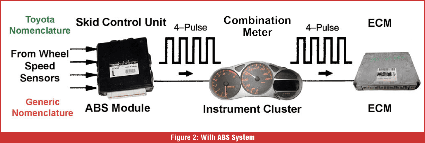
Staying with our Toyota example, when a P0500 Vehicle Speed Sensor fault would set on these models, the most common assumption was that it was a failed speed sensor on the transmission. It was easy to get to and fix the problem on older vehicles, or those that didn’t have ABS. However, for the ABS-equipped models, (Figure 2) the instrument cluster, or combination meter, acquired vehicle speed from the ABS module, which obtained its information from the wheel speed sensors. Once the cluster received this VSS data, it then sent it out to the ECM and sometimes the TCM. The transmission output speed sensor data is sent to the ECM/TCM. That allows the ECM/TCM to compare vehicle speed data with OSS data. After crunching the numbers (including tire size and final drive ratio), it can interrogate the VSS data to confirm its validity. On these models, the P0500 DTC is telling us that the VSS data and the OSS data don’t align. Failure points can include wheel speed sensors, the ABS module, the Instrument Cluster, the ECM, or the OSS.
This system, introduced by Toyota, came out over 20 years ago, as did Nissan’s version. Newer designs work in a similar way, although most manufacturers do not use the instrument cluster to perform VSS calculations; instead, they receive the calculated VSS data from another module.
Fault Logic and False Alarms
As you can see, the system has many components that must work together to determine an accurate vehicle speed. The speed accuracy is used for transmission shifting, anti-lock brakes, airbags, engine emissions, and navigation systems. The more parts involved also means there are more potential failure points. The way the ABS systems function, they can provide incorrect data due to a faulty wheel speed sensor signal that might set gear ratio faults in the transmission, yet not set a fault in the ABS module.
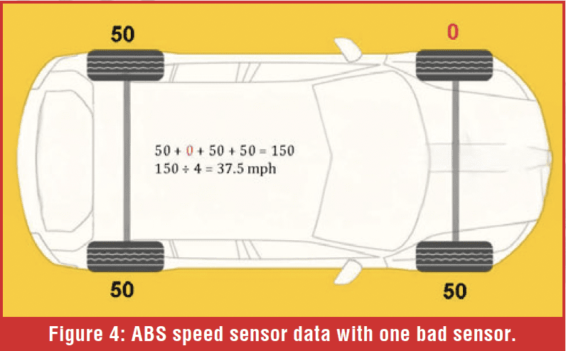
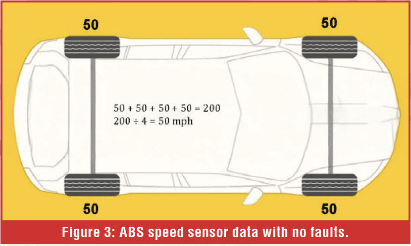 Why is there no speed sensor fault? It may be that sensor loss doesn’t occur long enough to qualify as a fault, yet that sensor’s data is still calculated into the batch data of all the wheel speed sensors. Or there’s EMI interference to the sensor. On a Toyota or Lexus vehicle, the P0500 may only occur after 5 seconds of signal loss. Let’s look at some simple math. On a vehicle with four-wheel speed sensors all reading 50 mph, the average of the four sensors is 50 mph (Figure 3). If one of those sensors loses signal and reads 0 mph, the average is now down to 37.5 mph. (Figure 4)
 When the PCM/TCM receives this VSS data and compares the engine speed and the commanded gear of the transmission, it will notice that the engine is running much faster than it should for the given road speed. Remember how those early designs set gear fault codes? That coding is still present in many of today’s designs, regardless of how many speed sensors are in the transmission. If the engine speed exceeds the expected value, the computer will set a gear ratio DTC.
Logically, for the computer, the problem must be a slipping clutch or a failed solenoid. Meanwhile, in the real world, the driver never feels a slip, downshift, or any change to the transmission until the check engine light comes on.
Essentially, it comes down to this: while the ABS is watching sensors and keeping time, it is still using that data to determine vehicle speed. The point I’m making is that if you have ratio faults, especially in the higher gears, and you or the vehicle owner has not felt any change leading up to the code setting, then you need to investigate ABS wheel speed data and watch for variations.
But why doesn’t the ABS module set wheel speed sensor codes if there’s a fault with a sensor? Sometimes they do, but frequently, you get a transmission-related code first. The reason for this is that the time a fault must be present to be recognized varies from module to module and function to function. A ratio fault in the transmission typically has a fault time of 0.3 seconds. The ABS wheel speed sensor fault time may be significantly higher. The P0500 VSS fault code on a Toyota has a 4-second window before the code is set. There is a valid reason to have a longer time to set a DTC, and that is rough roads. When the wheel rapidly rises and falls and vibrates due to the road surface, it causes a variance in the speed sensor data. To prevent false DTCs, the time to recognize a fault is extended.
When People Get Involved
What about the human factor? What can we do that might cause VSS issues? One common issue is oversized tires. A greater rolling circumference will give us a lower rotational speed on the drive train, reducing engine speed. The problem in this scenario is that the transmission may not shift into higher gears or downshift while driving at higher speeds. A common example is Jeep Wranglers with 42RLE and 35” tires not shifting into 4th gear at 45-50 mph or dropping back to 3rd prematurely. The solution in these cases is to re-gear the differentials to bring engine speed back up.
Another self-inflicted injury is when a transmission is swapped with a used but mismatched final drive. A typical call to the Hotline a few years ago involved Ford Transits with the 4F27E transmission. The 2.0 engine used in the Connects was the same as the 2.0 engine used in the Ford Focus. However, many of those Focus models had a different final drive ratio. Most of the calls we received had complaints about P0732 (2nd gear ratio) and P0733 (3rd gear ratio). Running on the lift, wheels off the ground, the codes frequently did not set. However, once the van was test-driven on the ground, it would often set the fault on the first upshift.
Another transmission swap issue may be simply that the calibration of a replacement transmission or TCM doesn’t match the vehicle. Most of the time, the calibration mismatch does show up as a DTC for a configuration fault, but there are those rare cases where everything just works right; the engine starts, the transmission shifts, but the VSS data shows a lower speed than the OSS data indicates. Reprogramming the TCM to the correct calibration may be a corrective course. Unfortunately, this is becoming increasingly difficult to do as manufacturers have been restricting the use of used modules by not allowing reprogramming if the VIN data does not match that of the current vehicle.
The next time you get a vehicle in with gear ratio faults but the transmission lacks evidence of slippage, don’t forget how the vehicle speed system works. Your problem may be outside, way outside, the transmission.