It’s been a while since our last look at electrical theory and diagnostic procedures, but a recent look back at some of those articles revealed a few issues that never made it to print. Hopefully you remained current with the concepts we talked about in earlier articles, because those points will remain an important part of these later articles, as well as your regular electrical diagnosis.
In this issue, we’re going to look at one of the most important diagnostic procedures you can use for identifying electrical circuit problems: the voltage drop test.
Let’s start by clearing something up right away: All voltage measurements are voltage drop tests. Whenever you connect a voltmeter to a circuit, you’re looking for the difference in voltage between the connection points; that is, the drop in voltage between the positive lead and the negative lead.

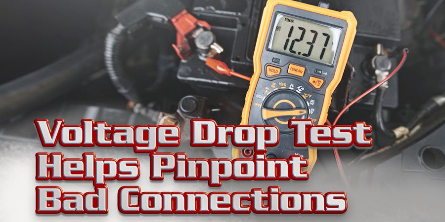
 So when you measure the battery voltage, you are in fact performing a voltage drop test. You’re measuring the drop in voltage between the battery positive terminal and the battery negative terminal (figure 1). Nothing mystical here.
The difference between a standard voltage measurement and what we think of as a voltage drop test is that, with the voltage drop test, you’re usually looking for a drop in voltage where there shouldn’t be one. That’s right: During most voltage drop tests, a good circuit won’t use any voltage between the points you’re measuring. If you do find a voltage drop, it indicates a problem in the circuit, such as a loose connection or corrosion, adding unwanted resistance to the circuit.
WHY A VOLTAGE DROP TEST?
Okay, so we have unwanted resistance in the circuit. Why can’t we just use an ohmmeter to check for the resistance? Or check the current draw, and use Ohm’s Law to identify a problem?
Both valid points. But an ohmmeter checks the circuit using low voltage and amperage levels. A problem that affects a loaded circuit might not appear at all using an ohmmeter. A common example is a frayed wire, where only one or two strands of the wire are left to conduct the current. An ohmmeter wouldn’t reveal this problem, because it doesn’t apply enough of a load for the frayed wire to cause a resistance loss.
![]()
And while an ammeter will indicate a problem with the circuit, it won’t let you pinpoint the problem the way a voltage drop test will. Remember, current flow is constant throughout a simple or series circuit, and on the common points in a parallel circuit. That’s why you can measure amperage nearly anywhere in the circuit. So, while the problem will show up with an amperage test, pinpointing the root cause of the problem will require a voltage drop test.
Let’s look at a common voltage drop test, and see what makes it so different… and so valuable.
PERFORMING A VOLTAGE DROP TEST
Probably the most important point to remember — and the one that’s most often forgotten — about a voltage drop test is the circuit must be loaded for the test to work. In fact, to get the best results, it should be loaded to the maximum level.
So, if you’re checking the circuit for a transmission shift solenoid, that solenoid must be energized for the voltage drop test to have any meaning. In the case of a starter circuit, the starter must be cranking during the test. For a fan, the fan motor should be set to run at maximum speed. If you don’t energize the circuit, the test results won’t have any meaning.
Another point to consider is which way you connect your meter leads depends on which side of the circuit you’re measuring. Always connect your positive meter lead closest to the positive circuit source.
So if you’re checking the positive side of the circuit for a voltage drop, you’ll want to connect your meter’s positive lead to the closest point in the circuit to the positive lead. On a starter circuit, that’ll usually be the positive battery post. For other circuits, that may be at a power source from a fuse, relay or computer.
When measuring the negative side of the circuit, you’ll want to connect your voltmeter’s positive lead closest to the load for the circuit you’re checking; the closest point to the positive source. On a starter, that’d be the starter case itself.
On a transmission solenoid, where you connect those leads to check the ground circuit depends on how the solenoid receives ground. If it’s a feed-controlled solenoid that’s grounded to the transmission case, the closest point to the positive source may be the solenoid or transmission case. If it’s a ground-controlled solenoid, the closest point to the positive source would probably be the transmission case connector.
 Let’s go over the steps for a basic load test, and see how to track down a circuit problem. For this example, we’ll use a starter motor, because it’s so easy to see the terminals and connections.
Step 1: Connect your voltmeter’s positive lead to the battery positive post (figure 2).
Diagnostic Tip: Most of the batteries today have two terminals; a top mount and a side mount. This is a great advantage for performing a voltage drop test. Connect your meter positive lead to the unused terminal: This lets you measure the voltage drop starting directly at the battery terminal, so you can take a good measurement from the terminal ends; a likely source for corrosion.
Step 2: Connect your voltmeter’s negative terminal to the point closest to the circuit load. On a starter, that’ll be the starter power terminal (figure 3).
Diagnostic Tip: On some circuits, it may be easier to use a piercing probe to reach the point closest to the load. Just remember to seal the wire when you’re done.
 Step 3: Load the circuit and check the voltage. On a starter circuit, that means you’ll have to crank the engine just long enough to record a stable voltage measurement.
Caution: Always disable the fuel pump and ignition before cranking the engine to perform a voltage drop test. Disabling only the ignition will allow the fuel system to flood the engine, which will damage the catalytic converter. Disabling only the fuel system could allow the engine to start on gas that’s puddled in the intake, ruining your test results.
Oh, and once you’ve taken the voltage measurement, stop cranking the engine.
Step 4: Record the voltage shown on your meter while the circuit was energized.
If you see zero volts on your meter, that part of the circuit is okay, and there’s no reason to check it further. In fact, on most circuits it’s okay to have up to 0.1 volts drop on each side of the circuit; that’s 0.1 volt on the positive side, and 0.1 on the negative side. Anything more than 0.1 volts indicates a problem. If you see excess voltage drop:
Step 5: Move the meter negative lead back to the next connection point on the circuit. In the case of the starter circuit, that’d be the positive cable connector at the starter power terminal.
Step 6: Crank the engine, and record the voltage shown on your meter.
If the voltage drops back to zero, you found the circuit problem: It’s in the connection between the cable connector and the starter power terminal. Remove the cable, clean the connection, and perform steps 2 and 3 again. The voltage should be zero.
 If the voltage drop still appears on the meter:
Step 7: Move the meter negative lead back to the next connection point in the circuit. In the starter circuit, that’d be the battery connector clamp or terminal (figure 4).
Step 8: Crank the engine, and record the voltage shown on your meter.
If the voltage drops back to zero now, the problem is in the positive battery cable between the last two test points you checked. Replace the cable and recheck the voltage drop at the starter terminal.
The whole point of the voltage drop test is to keep moving the test lead back along the circuit, until the voltage drop disappears. The circuit problem will be somewhere between that point and the previous test point in the circuit.
THE THEORY BEHIND A VOLTAGE DROP TEST
So why are we so concerned with a little bit of voltage drop in a circuit? To answer that, we need to go back to our earlier discussions about the principles of simple and series circuits. Probably the most significant of these principles when looking at a voltage drop test is Principle 6 for Series Circuits:
Each resistance in the circuit will use its share of the applied voltage, depending on its resistance. The sum of the voltage drops across the individual resistances will equal the applied voltage.
So any voltage drop, anywhere in the circuit, must be caused by a resistance in that circuit. That could be a planned resistance, such as the resistances found in a series circuit. But the object of most voltage drop tests is to identify and isolate unplanned or unwanted resistances, such as a bad or corroded connection in the circuit.
These faulty connections create an additional resistance in the circuit. And because that resistance is using “its share of the applied voltage, depending on its resistance,” it’s using up some of the voltage that the other, planned resistances need. Which means the circuit or component may not operate the way it’s supposed to. And too often, those components end up getting replaced for no reason; there’s nothing wrong with them. They’re just not receiving enough voltage, because something else in the circuit is stealing some of the voltage away from it.
Diagnostic Tip: Another source of unplanned resistance can be inadequate wire gauge; that is, the wire’s too thin to handle the circuit’s current requirements. Suspect this as a possible problem if someone has worked on the circuit before.
This is why a voltage drop test is so valuable. It allows you to identify faults in virtually any circuit, based on a simple electrical measurement: voltage. And it’s why a voltage drop test should be one the first tests you perform when looking for a problem in any electrical circuit.