When diagnosing transmission and driveability issues, it’s important to understand the computer systems that control them. Using multiple control modules allows vehicle manufacturers to fine-tune controls for the different systems.
But all those extra computer controls add to the vehicle’s overall weight. A typical, late model vehicle can contain up to two miles of wiring, weighing up to 150 pounds! Single sensors have multiple modules requesting data, which requires extra wiring and troublesome splices. More wiring harnesses were added to carry sensor information to multiple modules.
To minimize wiring, manufacturers began using a data bus. So, instead of running individual wires to each module from a shared sensor, the sensor information travels in a ‘package’ on a data bus line. Let’s look at how this system works:
Data bus systems consist of three major components: the modules, the nodes, and the wires (figure 1) . The node is usually part of the module. The node is basically a communication center responsible for sending and receiving data messages.
Here’s how the system operates: Suppose you have a mass airflow sensor that’s wired directly into the ECM. The TCM also needs information from this sensor, but it isn’t wired to the TCM. The ECM encodes the MAF sensor information and sends it to the node, which forwards it across the network. The TCM receives this data through the node and recognizes it whenever it’s available on the network.
Of course, there’s a time lag with this process, but it’s milliseconds; like the amount of time it takes from when you flip a light switch and the light comes on.
This information updates frequently, depending on the program installed in the modules and the baud rate (speed) of the bus network.
The automotive industry has used bus architecture for almost 40 years, during which time it has undergone many changes. Early networks were primarily single-wire systems. As the systems evolved, manufacturers added multiple networks and then introduced two-wire systems.
Today, high-, medium-, and lowspeed networks control virtually all parts of the vehicle. Critical driveline control functions always use highspeed networks.
For simplicity’s sake, we’ll discuss the latest, high-speed bus network. These latest bus networks are called CAN, or Controller Area Networks. The CAN system primarily uses a two-wire, twisted-pair, bus configuration. Most of these systems have three or more modules tied to the bus.
Each module usually has a node built into it. The node is responsible for sending and receiving information on the bus network. It’s programmed to acknowledge only the information that’s necessary for its module to function correctly and send information at a predetermined interval.
On some systems, a node may be present without a module. In those cases, the node will act as a gateway, providing access to the bus through an interface, such as the diagnostic link connector (DLC). It may also control bus traffic by prioritizing data according to importance.
There are several different types of bus networks in three different formats (figure 2):
- Star System
- Ring System
- Bus SystemSome manufacturers use a combination of these systems, known as hybrid CAN systems. Each system has advantages and disadvantages. Knowing what system you’re diagnosing is important in understanding how to isolate a problem. Let’s take a general look at these individual systems.
STAR SYSTEM
The star system uses a central, or gateway, module to control bus traffic, by transmitting the most important messages first and the lesser ones as space becomes available. The gateway module will often allow access to the bus by scan tools and programmers through the vehicle’s diagnostic link connector.
The star system produces a “role call” for all modules after startup, to make sure each module is awake and communicating properly. If one of the modules doesn’t wake up, the system will set a U-code, which makes it easier to pinpoint the problem.
Even if a non-gateway module fails, the network usually continues operating. On the flip side, if the gateway module goes down, it’ll affect all of the other modules.
A star-type system will have a static system resistance of about 100 ohms; maybe slightly more. Each module will have a set, nominal resistance that’s determined by the manufacturer, the network structure, and how many modules are in the system.
RING SYSTEM
The ring system is unique in that, if a module or wire is disabled, the other modules can still communicate on the network. Unfortunately, this does make it difficult to find a wiringrelated failure in the network.
Performing an OBD-II generic scan on this type of system is extremely important. If one of the modules has a problem, the other modules will store U-codes pointing to the problem area. It isn’t uncommon to have a TCM communication code in the ECM or vice-versa.
Since this system doesn’t have a gateway module, it relies on the “buddy system” to ensure modules are awake and communicating properly.
BUS SYSTEM
The bus system is the most popular system on today’s vehicles. It offers the greatest versatility and opportunity for expansion without having to rearrange the network. In a bus system, all modules are connected parallel to the bus, and communicate by “labeling” the information placed on the bus so that modules that need the information can identify it and retrieve it.
Diagnosing a bus system can be misleading if you don’t understand its architecture. Let’s take a closer look:
A bus system can have almost an unlimited number of modules communicating on it. The actual bus, or communication lines, act much like the old telephone “party line” system. All of the modules on the bus can “hear” all of the information sent on the network, but they’re assigned to “listen” only to the messages that they’re programmed to receive.
For example, if the ECM is sending a message about MAF readings, the TCM will listen to this information, while the BCM and the ABS modules may not.
With this information in mind, a module can generate diagnostic codes when it isn’t receiving information from the bus. Communication codes that indicate faults for specific modules are generally found in companion modules.
For example, if the TCM isn’t communicating, the ECM or the BCM may store a code, while the TCM may not store any codes, due to an internal or wiring fault.
When diagnosing these systems, try using the OBD-II generic or global mode instead of VIN specific ID. Sometimes communication codes won’t show up under the VIN specific protocol on some aftermarket scan tools.
BASIC DIAGNOSIS
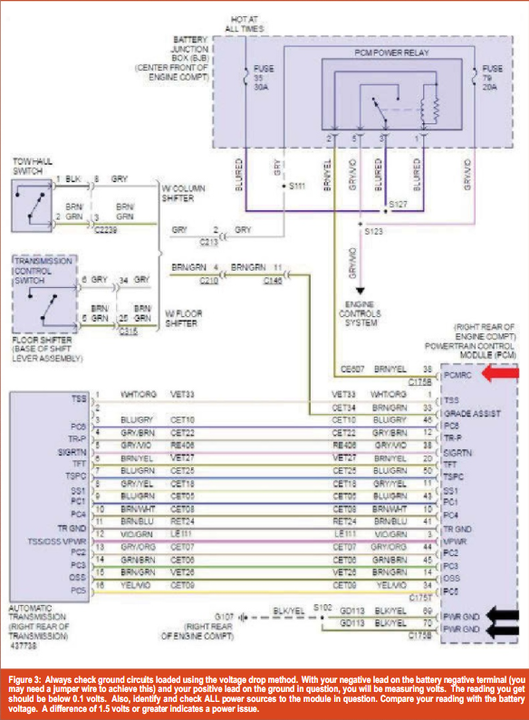
If one of the modules isn’t communicating, first verify power and ground to the module. Using an accurate wiring diagram, perform voltage drop tests on all the ground terminals KOEO (key on, engine off) or KOER (key on, engine running), using the vehicle battery as your ground reference (figure 3).
Then perform voltage drop tests to all incoming power sources during KOEO, cranking (monitoring the lowest voltage obtained during cranking), and KOER.
During the cranking test, voltage should never drop below 9.5 volts. You’ll need to use a quality digital multi-meter: Test lights and power probes are out of the question. A graphing voltmeter or oscilloscope is very useful for monitoring cranking and KOER voltage, making spikes and dropouts easier to observe.
You’ll need to backprobe the circuits and make accurate measurements. Some systems don’t tolerate supply voltages less than 12 volts. Correct all discrepancies, clear codes, and retest before condemning a module.
The standardization of CAN systems is a fuzzy science. While they all have some similarities, there are differences that can lead you to misdiagnosis and costly module replacement.
While most manufacturers have gone to the two-wire, twisted-pair format, bias voltages and terminal resistor locations have been modified to fit their own unique systems (figures 4 and 5). There are only a few standardized tests that can be performed on all CAN bus systems with patterned results. 
Now that we’ve laid the foundation for understanding CAN bus systems, in the next issue we’ll deal with diagnosing and repairing these systems.