
We’ve all felt challenged about problems with transmissions we’re unfamiliar with, and CVTs top the list. As different as these transmissions seem, there are a few “quick” tips and checks you can use to get through the diagnostics.
In this article we’ll cover the Jatco CVT transmissions, and look at some ways to make this a winner for your shop.
Finding information has been a bit of a problem but it’s getting easier every day. There are many sources out there such has webinars, bulletins, seminar books, Gears magazine articles and VTS training videos on the Jatco CVT transmissions – and that’s just from ATRA.
 Nissan offers free service manuals online; just google “Nico Club Nissan service manuals”. This will bring you to the Nico Club or you can go direct to website https://www.nicoclub.com/nissan-service-manuals.
These factory manuals are very useful for looking up codes and information. Once you select the vehicle you’re working on you’ll see a long list of PDF files. The transmission manual is labeled “TM”. One of the best parts of a factory manual is that it shows what conditions will set a code. In some cases it’ll even show you the exact voltage that triggers the code.
The system description section shows how the system works and is great for understanding transmission diagnostics. To break it down further, the control system section tells you about each input and output that is used to control the CVT transmission.
Like so many other manufacturers, you might have a transmission problem due to low battery voltage or DTCs from other systems; about 60% of ATRA calls I field on these transmissions wind up being due to a bad battery or problem in another system so make sure you do a battery test and check the other systems for codes before doing any work on the transmissions. Common problems I see are with ABS codes and wheel speed sensors.
The manual will usually have a list of all the factory PIDs and what they mean. The descriptions are a bit tricky though so take your time in understanding their meaning. You can have something like “shifting doesn’t finish”, which actually means that it’s slipping or has a ratio code. Understand that these are Japanese translations and they don’t always use our terms and meanings. That’s ok, it’s still better than much of what’s out there. Here are a few PID descriptions that’ll help make it easier for you:
- VENG TRQ Display the engine torque recognized by TCM.
- PRI TRQ Displays the input shaft torque.
- TRQ RTO Displays the torque ratio of torque converter.
- PVING VOLT Displays the battery voltage to the TCM.
- ISOLT1 Displays the command current from the TCM to the torque converter clutch solenoid.
- ISOLT2 Displays the command current from the TCM to the line pressure solenoid.
- SOLMON1 Monitors the current from the TCM to the torque converter clutch solenoid.
- SOLMON2 Monitors the current from the TCM to the line pressure solenoid.
- ENGBRKLVL Displays the setting of engine brake adjust in “Work Support mode”
One thing nice with all the PIDs is they have a check system, kind of like a Dodge 48RE governor sensor. There may be a primary and/or secondary pressure sensor on many of the Jatco CVTs. Some models just use one sensor.
 On the scan tool in the data section most scanners have a PID called ISOLT1 which is the TCC solenoid. Displayed is the commanded amps out of the TCM. The TCM makes sure there are no issues with wiring or the solenoid by monitoring the amps in the circuit. The PID is Solenoid Monitor 1.
In figure 1 on the top left you have the TCC solenoid amps (ISOLT 1) and to the right is monitoring the amps on TCC solenoid. As you can see the amps graphed out are the same in both pictures. This is a correct reading; you want the graphs the same and the amps should be very close at all times.
Still with figure 1 bottom left is primary pressure solenoid (ISOLT 2) amps. This is what the TCM puts out to the solenoid. To the right is Solenoid monitor 2. These should always be the same amps.
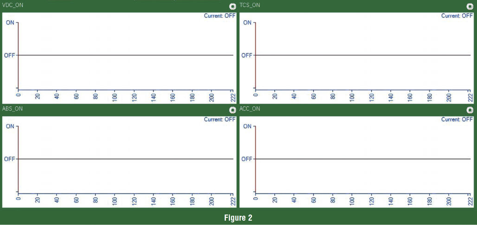
You’re likely to get a car in that feels like it is starting in the wrong gear, no engine response and loss of power. One quick and easy way of finding what’s wrong is to graph out VDC_ON, TCS_ON, ABS_ON and ACC_ON (Figure 2). All these PIDs should stay off, if they don’t then there is a code in the system. Many times, wheel speed sensor cause ABS and traction control to cut power to the engine.
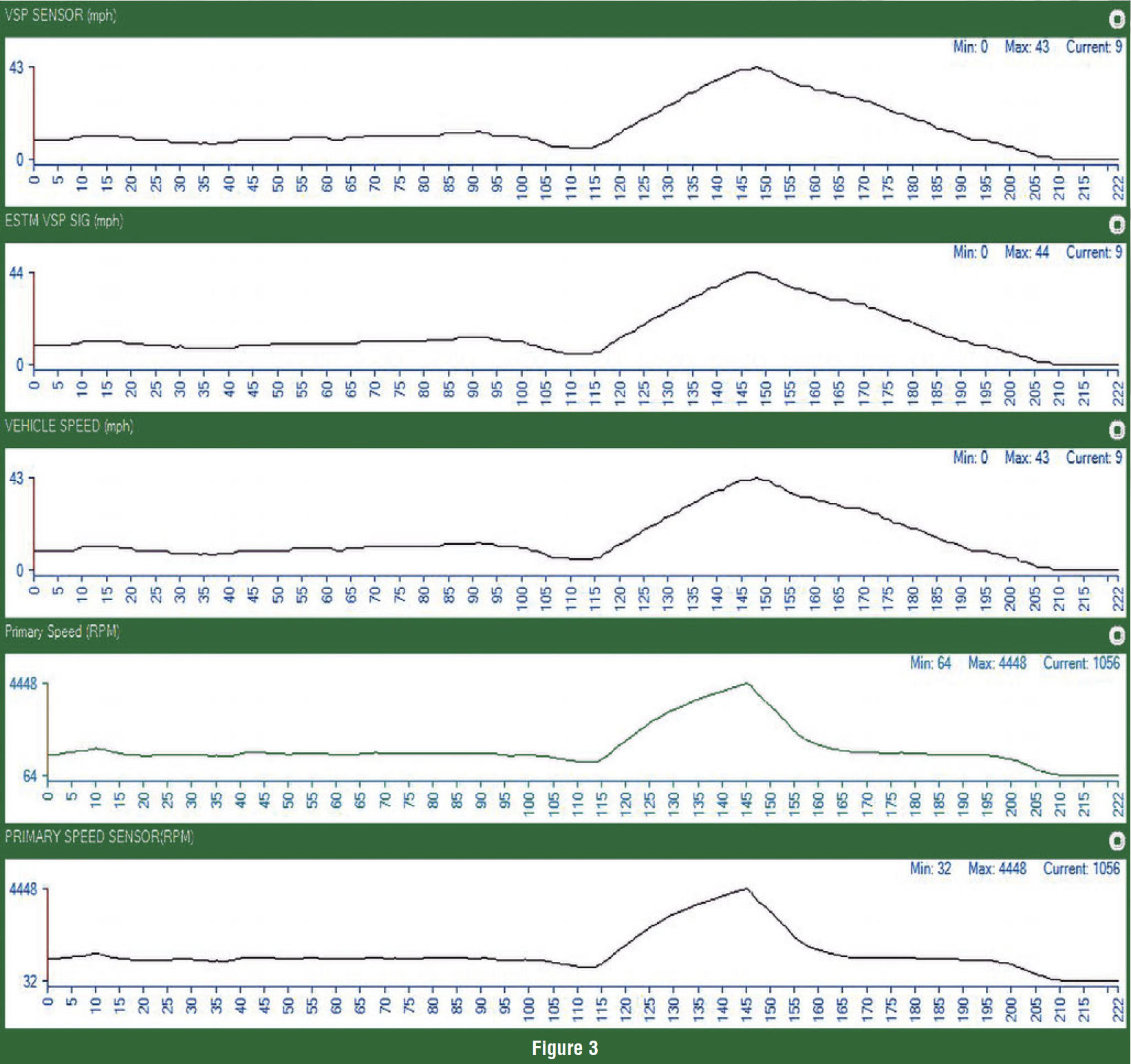
Speed sensor are always a main input to the TCM for shift feel and ratio change. I feel it is always best to graph them out to compare. One nice thing Nissan did was to have two pids for each sensor. One pid for the speed sensor and the other is what the TCM is seeing.
The VSP Sensor is from the secondary pulley on most units (figure 3). ESTM VSP SIG is estimated vehicle speed sensor, it uses the ABS wheel speed signals as a back up signal. VEHICLE SPEED is coming from the ABS module. So when diagnosing speed sensors look at all three they should be matching. Be careful here, some scan tools report from the wrong sensor for VSS so, here again, check the vehicle speed in ALL the modules. Same thing with temperature readings some have a temp gun handy as a backup.
 Remember to check for TSBs on every car you work on. Here is a free website that that is loaded with information: http://www.bbbind.com/tsb-and-wiring-diagrams-login/
You’ll have to sign up for it but it’s free and never sends out junk emails.
While we’re at it, this website is great for looking up recalls that might affect your work. Not to mention, what a service it is for your customer. https://www.nhtsa.gov/recalls.
There’s another website I’d like to share from OEM1STOP. It’s great for looking up programming and updates. https://oem1stop.com/
Diagnosing problems and failures are easier once you develop a plan. When you stick to the basics, you’ll usually find it.


