The 9T series transmission is General Motors’ version of collaboration with Ford for a next-generation powertrain solution. While Ford chose to stick with an 8-speed, GM opted for a 9-speed unit. Since its introduction, the 9T50 has become the mainstay for GM’s front-wheel drive livery. With over half a decade of history, these units are coming out of warranty and requiring attention in the aftermarket realm. Let’s take a journey through the various concerns that bring these transmissions into the shop.
UNIT IDENTIFICATION
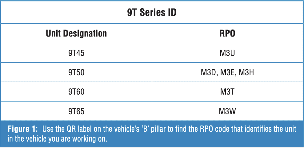 The 9T series encompasses a wide range of engine applications and therefore features several variants (Figure 1). The digits after the 9T designation specify a relative input torque capacity; the higher the number, the greater the torque handling capability. Most of the variance lies in the number of clutches contained in each clutch pack. However, gear ratios on the transfer and output gears vary depending on the application.

PROGRAMMING
Vehicles equipped with the 9T-Series transmission should always be checked for possible programming updates before working on the unit, especially when there are shift quality or other operational issues. Some concerns that are remedied by updated TCM programming are as follows:
- “Transmission HOT, Idle Vehicle” message in the DIC.
- Burnt 3-8 clutches
- Harsh shifts due to commanded high line pressures
- Harsh and/or slipping shifts
- Erratic TCC apply
Another area of concern when diagnosing shift timing and quality issues is the use of standard powertrain strategies. The operation of the engine is closely intertwined with the TCM strategy. Additionally, other systems, such as the ABS, ADAS, BCM, and other modules, may also alter the way the transmission operates. Therefore, if there are conditions that need to be managed on the engine or other modules, the transmission may operate objectionably. Fortunately, most related concerns can be linked to diagnostic trouble codes in different modules. Always scan for all code in all modules at all times.
For example, a 9T-series equipped vehicle operating in a cold climate may experience restricted gear operation (no higher gear operation commanded) with no transmission DTCs. Here’s where the ECM strategy monitors ambient air temperature in vehicles equipped with a turbocharger and an intercooler, detecting freezing conditions. Suppose airflow through the cooler is restricted due to icing. In that case, a code P0299 (Engine Underboost) will be set, and the transmission will shift into a lower gear to increase engine RPM, thereby increasing air flow through the intercooler. Engine power will also be limited until the icing condition is remedied. Note that unless all modules are scanned for DTCs, the root cause would remain a mystery.
Another issue that may cause a customer to bring their vehicle to your shop is an intermittent neutral complaint, typically occurring on the 1-2 shift at light throttle. An observant driver may also notice that the driver information center (DIC) will momentarily display “Shift in Progress” and the “D” range indicator will flash, indicating the transmission is in neutral during the shift. Observing the shift command PID on a scan tool in TCM data will verify that the shift strategy programming indeed selects Neutral. This condition is normal. The strategy is designed to release torque from the Selectable One-way Clutch (SOWC) to enable a smooth 1-2 shift under low-load, light-throttle conditions.
 THE INTERNAL COMPONENTS
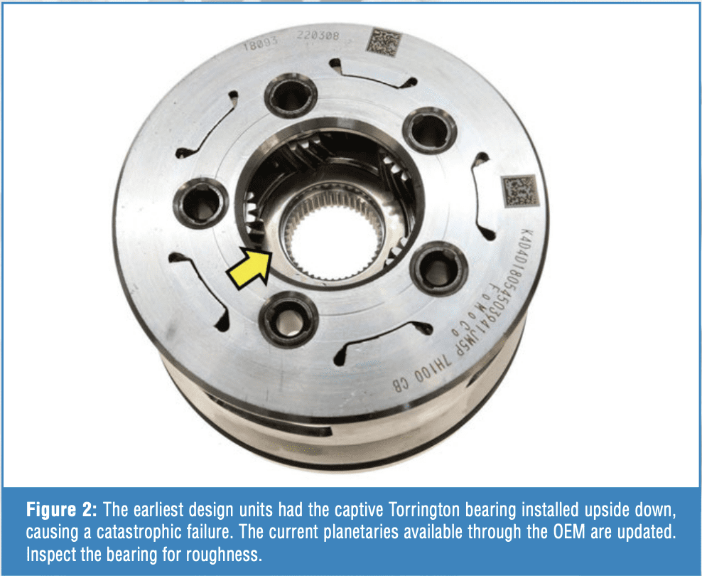
As we recall, the earliest units had output planetary failures. The affected part has since been updated (Figure 2). Always inspect the captive Torrington bearings in the planetary. It handles considerable load and stress since it is active at highway speeds.
Several units are now experiencing failure of the 4th clutch bearing. Use manual shifting to listen for elevated noise while operating the vehicle in 4th gear to isolate this concern.
The Torrington bearing has a unique duty in assisting with the application of a rotating clutch. The 4th clutch piston is stationary while the clutch drum rotates. The repeated loading and unloading of the bearing causes stress, eventually leading to failure. Damage to the 4th clutch and adjacent components is common. Replace and repair as necessary.
THE VALVE BODY
The valve body on shift-by-cable units tends to have fewer issues than those on ETRS (Electronic Transmission Range Select) or shift-by-wire designs. Once metallic debris makes its way through the unit, the valves can become stuck. However, the Hall-effect switches on the ETRS units tend to collect metallic debris on the magnet, compromising the operation of the switches. Additionally, debris can accumulate and obstruct the valves from fully opening and closing in the switch area, resulting in an inaccurate position being fed back to the TCM. Other failures in this area include the magnet inside the Hall-effect switch breaking, and the tip of the valve breaking off. Faulty system feedback data results in DTCs, and the unit is commanded to Park. Note that ETRS codes are set in the ECM. Scanning for codes will give you directions on the ETRS fault detected:
- P187E: Transmission Park Valve Stuck Off
- P18AA: Transmission Range Mode Control Valve 1 Position Switch Circuit Stuck On
- P18AB: Transmission Range Mode Control Valve 1 Position Switch Circuit Stuck Off
- P18AC: Transmission Range Mode Control Valve 2 Position Switch Circuit Stuck On
- P18AD: Transmission Range Mode Control Valve 2 Position Switch Circuit Stuck Off
- P18AE: Transmission Range Mode Control Enable Valve Stuck Off
- P27EC: Transmission Range Mode Control Valve 1 Position Switch Performance
- P27F0: Transmission Range Mode Control Valve 2 Position Switch Performance
Keeping a donor valve body with good parts can help resolve a targeted repair and get the vehicle back to the customer quickly.
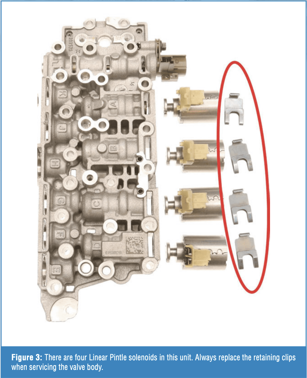
 Unlike GM’s 10-speed rear-wheel drive units, the 9T series valve body utilizes a combination of linear pintle and conventional pulse-width modulated solenoids to control unit hydraulics. The Linear Pintle solenoids share the same retaining clip as the GM and Ford rear-wheel drive 10-speed transmissions and are prone to failure. The retaining clips lose their tension, allowing the solenoid to move in the bore during operation, resulting in harsh or flared shifts. Always replace these clips when servicing the valve body or rebuilding the unit (Figure 3). The Ford part number HL3Z-7G007-A is available from the OEM and is compatible with this application. GM does not list these clips separately. There are also aftermarket service solutions available through your soft parts supplier.
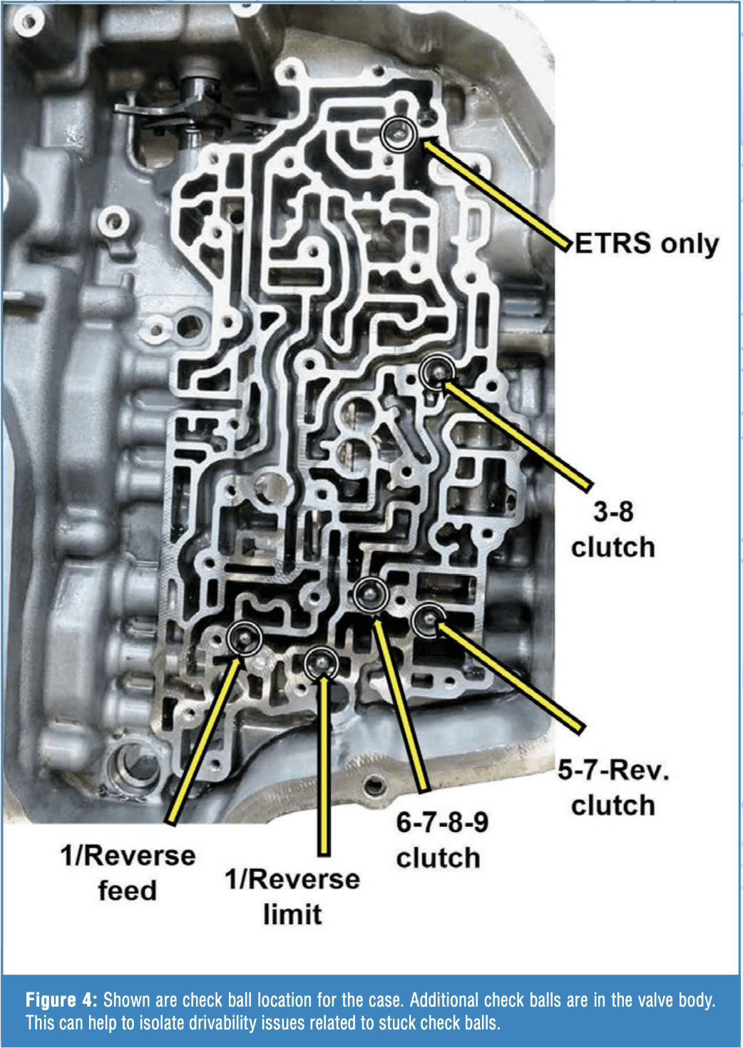
Another valve body-related concern is that check balls can become lodged in the separator plate. Drivability complaints vary directly with the hydraulic control circuit associated with the check ball (Figure 4). Always inspect check ball seat areas and replace the separator plate as necessary. Note that the OEM separator plates come with non-metallic check balls. Order a replacement separator plate using the VIN. Several applications have updated plates with special instructions included.
CASE WEAR
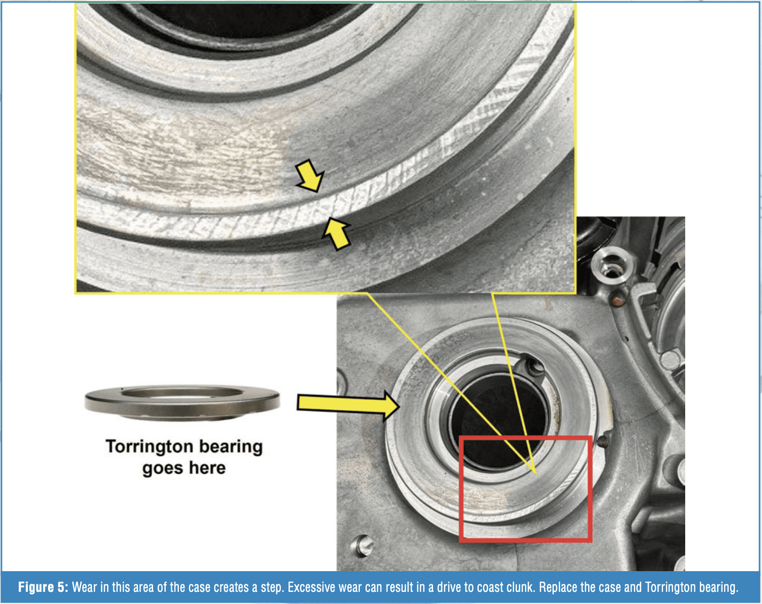
Concerns about case wear in the differential area are becoming increasingly common in units with higher mileage (Figure 5). A similar issue occurs with the 6F35 transmission. However, currently, there is no aftermarket repair for the 9T series units. You must purchase a new or good used case. The current list price is approximately $300 USD. Order by vehicle application. Also, replace the differential Torrington bearing.
STUCK IN PARK
Vehicles equipped with the drive-by-wire unit may experience a complaint of being stuck in Park. Often, the car will be dropped off at your shop, blocking your bay doors or the main driveway after hours by a tow truck operator. Before you panic, attempt to operate the vehicle. If it does not move, use the following procedure:
- With the vehicle running, press and hold the service brake.
- Select Drive or Reverse by pushing and holding (push-button design), or depress the shifter button, then hold in the selected range. This will place the unit in ETRS override mode.
- If the vehicle can move, the ETRS will remain in override mode as long as you hold the selector in the desired direction of movement.
- Release the selector, and the vehicle should return to the Park position. If not, select Park before leaving the vehicle.
If the transmission experiences a catastrophic failure or the ETRS valves are stuck in a position that prevents movement, the vehicle will need to be moved manually. Most applications have a manual park release lever on top of the transmission.
Technology has delivered transmissions that offer nearly perfect shifts under most conditions. With time, shift consistency declines. That’s when we must determine what is going wrong, why, and correct it. Articles like this help us stay informed about items to address inside and outside these units, so we can deliver the goods to our customers with confidence that we did it right the first time.