The valve body used to be an assembly that got little attention during a transmission RDI (remove, disassemble, and inspect). However, since most late-model valve bodies are made of cast aluminum with Teflon-coated aluminum valves with pulse-width modulated solenoids attached, they’ve become a focal point for possible failures. Gone are the days of snapping valves with your pocket screwdriver. With technology pushing the limits of physics to produce the ‘perfect shift, always,’ the valve body is the center of attention of modern transmissions and the most likely part to fail first. In this article, we will explore the importance of inspecting the valve body, indicate areas of concern, and offer several inspection techniques.
FIRST THINGS FIRST
The process of evaluating a valve body involves the same three major steps as a transmission:
- Assessment
- Teardown and inspection
- Rebuild, rework, and replace necessary parts

The assessment stage involves verifying the customer’s complaint. The vehicle is your best dyno. So, make sure you don’t lay a wrench on it before you have convincing evidence leading you to do so. Operating the vehicle while observing sensor and output data is necessary to see if the transmission is responding correctly to commands. Using solenoid and clutch apply charts can help you isolate hydraulic, electrical, and mechanical systems that may be causing issues.
 For example, when assessing a vehicle equipped with a 10R80 transmission, use the solenoid ring chart to isolate possible faulty hydraulic circuit activity (Figure 1). A test drive of the vehicle may show poor shift quality each time shift solenoid C turns on or off. Note that poor shift quality often shows up as harsh shifts on late-model, clutch-to-clutch transmissions. Zeroing in on this during a test drive is valuable. Using a vehicle-specific wiring diagram, back probe, and verify the electrical signal to shift solenoid C with a Digital Storage Oscilloscope to ensure accuracy before condemning the valve body. If your circuit is responding correctly, now you have hydraulic and mechanical items to address in the valve body and/or the transmission.
So, if we drive this 10R80-equipped vehicle and notice poor shift quality on the 1-2, 5-6, 6-7, 7-8, and 8-9 shifts, we can look at the chart in Figure 1 and see that the Shift Solenoid C hydraulic circuit could have functional issues. Notice that each time the solenoid changes state (on or off), there is a critical amount of time during which the computer commands the clutch to apply or release. A sticky valve, a sticking linear solenoid, or a leaking accumulator in the clutch control circuit will cause poor shift quality that cannot be corrected through TCM learn procedures.
![]()
 Next, replace the solenoid with another in the valve body. It would be good to swap a solenoid with the same characteristics (if possible), but if the change moves the complaint to another shift sequence, you’ve found your problem. Always remember to mark all solenoid locations and return them to their original positions in the valve body. Replace solenoids with the same type and characterization numbers (Figure 2).
If the problem persists, the valve body needs to be closely evaluated for possible performance issues. Evaluating the valve body means checking the following:
- Solenoid mechanical function: A contaminated or damaged solenoid may stick or not control the hydraulic circuit properly. Thoroughly clean and check for freedom of movement of the solenoid pintle, valve, and proper sealing.
- Hydraulic circuit function: Worn or sticking valves will cause intermittent or consistent shift quality issues. Also look for excessive valve scoring, loose/leaking end plugs, and broken or collapsed return springs. Ensure that the casting passages and surfaces are not cracked or damaged. Look for undersized check balls, damaged check ball seats, or check balls lodged in the separator plate/valve body. Always use hydraulic diagrams (when available) to identify ALL components in a hydraulic control circuit, including accumulators, relief, and check valves. Missing gasket material and plugged orifices must not be overlooked.
Of course, with the valve body removed, you should perform an air check on the C-clutch to identify any issues inside the unit.
THE VALVE INSPECTION PROCESS
If your assessment leads you to remove the valve body for inspection, your procedure should be something that you can reliably duplicate. Here’s where practice makes perfect. Remember, you are trying to get to the root cause of the customer’s complaint. So, take time to hone the skill of assessing valve bodies like a fine craftsman.
The process of inspecting valve bodies is not standardized. However, you should choose a method that works for you. Determining whether a valve bore is excessively worn or a valve is damaged is critical to ensure a successful repair. In the absence of high-tech valve body test equipment, builders use three practical methods. Of course, there may be more that I am not aware of; however, the ones mentioned here are the most popular among seasoned technicians.
MEASURE AND COMPARE
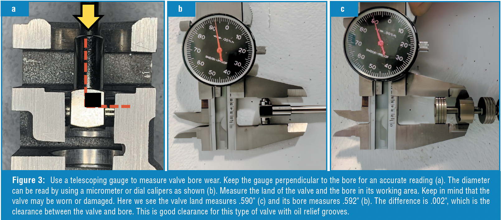
When in doubt, nothing beats a good old-fashioned measurement. Using a micrometer, dial calipers, and a bore micrometer, you can measure the diameter of individual valve lands and their respective bores and calculate the clearance (Figure 3). Ideally, valve clearance is between 0.0005” and 0.0016” between the valve land and bore surfaces. The clearance can be greater given the length, valve design, and hydraulic control circuit function. Using measuring tools requires finesse and consistency to ensure the measurements are correct. Also, care must be taken to measure the working area of the valve bore to obtain the dimensions of the most worn areas.
USE A VACUUM TESTER
Vacuum testing is another method to measure relative wear. The vacuum tester is a tool that provides the builder with the means to standardize testing processes and establish a pass/fail reading for a valve bore. Without getting into the specifics of how this works, this can be a beneficial process. However, you must keep in mind two critical items:
- You are using air to test a hydraulic circuit. Valve length, land dimensions, valve type, and valve position are variables that will impact the reading you obtain. Comparing a known-good valve bore reading with your results will yield a practical, real-world expectation. However, you must note that your readings will change if you are using a different design valve than the original.
- Consistent testing methods are necessary. It is not a contest to get the highest vacuum reading on your gauge! As a matter of fact, if the reading is too high, that could indicate an issue with the valve binding due to inadequate clearance. It is recommended to place the valve in the working area and use the wiggle-test method to obtain the lowest vacuum reading as your actual value.
So, as you can clearly see, it takes attention to detail to get good, trustworthy results. Just like any other tool in your toolbox, it is only as good as the user.
EYEBALL IT!
 Here’s where old-school technicians come into play. Although this is a less scientific method, it may be beneficial to technicians who have a feel for good versus bad. Here are a few techniques that I’ve observed throughout my years as a builder:
- Use a flashlight on the valve body with the valve resting inside (unloaded). Remove the return spring and ensure the valve is in its working position. With the end cap removed, look into the valve bore to see if there is excessive light passing through (Figure 4).
- Use hook scribes to rock the valve side to side and up and down in the bore to ‘feel’ for relative wear (Figure 5). Take care not to damage the coating on aluminum valves. It is helpful to spray some ATF in the valve bore. You can see more, relative fluid displaced as you move the valve up and down when there is more wear present between the valve and bore.
- Remove the valve from the valve body, clean and dry the valve body casting, and use a bore scope to inspect the areas in question (Figure 6). Wear will show up as shiny spots or severe gouges. If the shiny areas exceed 1/3 of the circumference of the land, there is a high probability that the bore is excessively worn. Further assessment is recommended.
 The unfortunate downside to the procedures just mentioned is that they rely on a qualitative assessment to determine the integrity of the valve body. While one can ‘train’ themselves to recognize what good and bad look like, the margin of error is much higher than when using measuring devices.
In the end, you must determine which method or combination of methods works for you. Remember, you need a process that can be easily duplicated so you can compare past results.
PATTERNED FAILURES
 With all the troubles that can arise from missing a critical worn valve bore during the repair process, many builders throw off their inspection hats and simply replace certain valve bodies. While in some cases this may be a wise call, this should not be the rule. Whenever you are dealing with a transmission you have not built before, it is a good practice to contact the OEM parts department for price and availability on a new valve body. Note that if the price is oddly low and they have a few in stock, this is likely a problematic component that you should replace on your rebuild.
However, when you have a unit on your bench with a valve body in questionable condition, keep in mind that most manufacturers have similar hydraulic control valves with a similar frequency of use. With that in mind, inspecting the valves from ‘busiest to the least busy’ is a reliable way to assess a valve body for reconditioning, especially when dealing with high-mileage vehicles. Here’s a list of valves from busiest to least busiest:
Pressure Regulator and Boost Valves: The pressure regulator valve is one of the first valves to receive oil from the pump. In most applications, it is responsible for maintaining line pressure and charging the torque converter. Most late-model applications use a line pressure accumulator to smooth the pulse-width-modulated oil signal from the control solenoid.
Solenoid Regulator Valve: Also known as Actuator Feed Limit, Pilot Valve, or other names. The solenoid regulator valve reduces the mainline pressure for feeding solenoids in the valve body.
Torque Converter Clutch Valves (regulator, enable, and modulated): These valves can be extremely busy on vehicles driven primarily in stop-and-go traffic. Late-model applications can command full or partial lock-up in second gear, and cycle partially on and off during shifts.
Accumulators: Most late-model applications have accumulators in hydraulic circuits with PWM solenoids. They act as hydraulic ‘shock absorbers’ to smooth out pressure pulses. They must not leak fluid past the valve. All bypassing oil goes to the sump, affecting the overall hydraulic circuit performance.
Once you have identified bores and valves that need repair or replacement, you must assess whether to proceed with a repair or replace the entire valve body. Remember, it is not just the cost of the parts but also the time needed for the builder to perform the repairs. Also, take into consideration the mileage and age of the unit. If the calculations are close, it may be better to get the OEM replacement, especially when solenoids are included.
As these newer units age and get into the higher mileage range, the likelihood of poor shift quality and inadequate TCC control increases. With valve body wear being the most probable cause, it is essential for transmission builders to identify and repair hydraulic issues efficiently. This article will help you in that area so you can deliver the goods to your customers with confidence!