

The Jatco JF017E transmission has been out for a while and many shops are already enjoying the extra profits that CVT rebuilds are bringing in.
The Jatco identifier is JF017E; Nissan calls it the RE0F010E, RE0F010H, and RE0F010J. We’re going to keep it simple and use the Jatco identifier.
The JF017E is a lot like the JF011E but with a few changes. They got rid of the stepper motor. To clarify the difference, we’ll go over the valve body and solenoid arrangement. Another change is they’ve added an input speed sensor. We’ll also cover the speed sensor locations and their operation.
The JF017E is a heavy-duty CVT that shows up behind 3.5L motors. It uses a chain rather than a belt used in the earlier models.
Look for the JF017E in Nissan Altima 2013-18, Nissan Pathfinder 2013-18, Nissan Murano 2015-18, Nissan Quest 2015-18, and Infinity QX60 2014-18 with the 3.5L engine.
AN OVERVIEW
The input speed sensor sits on the outside of the transmission facing the front of the car (figure 1). The input speed sensor is new to this model and reads the speed of the input shaft. This sensor gives the computer more information to improve transmission control.
The range switch is on the outside of the transmission and tells the computer the position of the transmission manual valve. The range switch also controls backup light operation and acts as a starter safety switch.
The JF017E comes equipped with a transmission warmer on most models. Jatco is trying to keep transmission fluid temperature consistent to help maintain consistent operation. The warmer also has a hose fitting for an external air-to-oil cooler. Keep in mind this is considered a heavy duty CVT; it has a tow/haul feature in some models. So an efficient cooling system is important.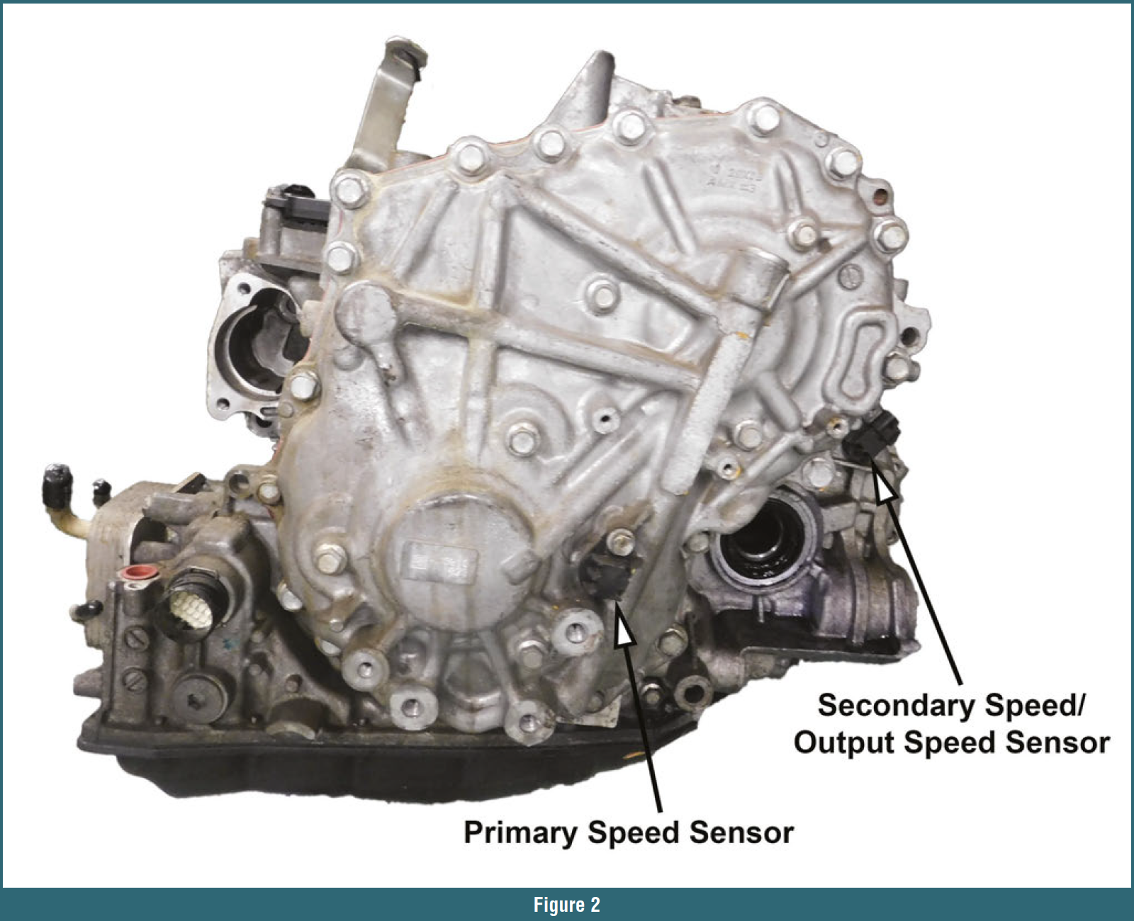
There’s a primary speed sensor on the rear cover that reads the speed of the primary pulley (figure 2). There’s another speed sensor by the differential. In some years and models they call this the secondary speed sensor; for other models and years they call it the output speed sensor. The output speed sensor reads off the differential ring gear.
All the speed sensors are three-wire, digital sensors. The power wire receives system voltage and the sensor produces a digital signal that returns to the computer through the signal wire. The final wire provides sensor ground.
Watch out for spacers under the speed sensors. Jatco uses the same speed sensors in several locations; the spacers are necessary to maintain the correct air gap. For now, we haven’t seen spacers under the JF017 speed sensors.
One other thing to watch for: All the speed sensor connectors are the same. Make sure to mark each connector during removal. It’s easy to switch the primary and secondary speed sensors connectors, and that’ll cause pressure solenoid and ratio codes.
VALVE BODY
The valve body has had some major changes on the JF017 CVT. First, notice that the pressure control solenoids have changed. They now look more like an Asian Warner linear solenoid. And there’s no longer a stepper motor or a ratio control valve arm to line up.
Let’s talk about the upper valve body and solenoid ID (figure 3). All the solenoid grounds are attached to the valve body. All of the solenoids are 5.5-8.5 ohms except the TCC solenoid, which is 6.1-7.7 ohms.
The secondary pressure, line pressure, and primary pressure linear solenoids are the same; only the select solenoid is different. The select solenoid is a normally high solenoid and it controls the forward and reverse brake clutch pressure.
The line pressure solenoid is a normally high solenoid that regulates oil pump discharge pressure to control line pressure.
The primary and secondary pressure solenoids are normally high solenoids, too. They regulate pump discharge pressure to maintain the correct oil pressure in the primary and secondary pulley oil circuits. This allows the primary and secondary pulleys to keep the chain from slipping and to control ratio change.
The TCC solenoid is a normally low solenoid. This is a pulse width modulated solenoid that controls lockup slip.
There are two pressure sensors on top of valve body. The primary pressure sensor is usually black. The other pressure sensor is the secondary pressure sensor. We’ve seen several different color pressure switches; your best bet is to use the same color switch unless you bought a valve body that’s been programmed correctly.
Take a look at the valves and small parts (figure 4). All four checkballs are for reverse and forward engagement feel. There’s one ball with a spring and that spring is easy to misplace. Install the spring first; then the ball.
There’s also a filter screen: The open end of the filter goes into the valve body first.
This valve body has a lot fewer valves than other CVTs. Pilot A valve reduces pressure for the primary, secondary, select, and line pressure solenoids. Pilot B valve reduces pressure to the TCC solenoid. The primary reducing valve reduces line pressure and adjusts primary pulley pressure.
There are five valves in the lower part of the valve body (figure 5). The TCC control valve lineup adjusts the torque converter release and apply pressures. The TCC regulator valve adjusts torque converter pressures. The pressure regulator valve adjusts pressure from the pump to create line pressure. The secondary reducing valve reduces line pressure and adjusts secondary pulley pressure.
As you can see, Jatco is making these transmissions simpler and controlling them differently. This valve body only has eight valves. There’s one more valve in the pump called the flow control valve that sometimes has problems with wear and sticking. Always inspect the flow control valve on any Jatco CVT you pull apart.
In upcoming issues, look for more articles on the internals for this transmission. And, in the meantime, keep fixing the Jatco CVT and making that extra money.


