Ten-speed transmissions have been with us for a half-decade now, and they are coming into transmission shops around the world. With these units coming out of dealer warranty, they will end up in your shop sooner rather than later, needing diagnosis and repair. Since there are so many layers of technology to consider, correctly diagnosing these units can be tricky. This article will look at diagnosing issues with the General Motors 10L series transmissions.
IS THE PROBLEM OUTSIDE THE BOX?
When dealing with the GM 10L series unit, the first question you must ask is whether the problem is outside of the transmission. Given the numerous interactive strategies for managing the powertrain, you must be a detective to ensure that nothing is overlooked.

The first order of business is to identify the unit. Different strategies are used for different versions, which means the TCM strategy may induce things like failsafe modes and no-move conditions. So, let’s approach this unit in an orderly fashion to address the easiest items before we lay a wrench on it.
 IDENTIFY THE UNIT
Not all 10L units are identical. Several variants have been added since the first 10L80 that showed up in the 2019 Camaro. While the basic transmission functionality remains the same, minor changes can throw your diagnosis into a tailspin. Let’s look at how to identify these variants and the changes that matter most when attempting to isolate an issue.
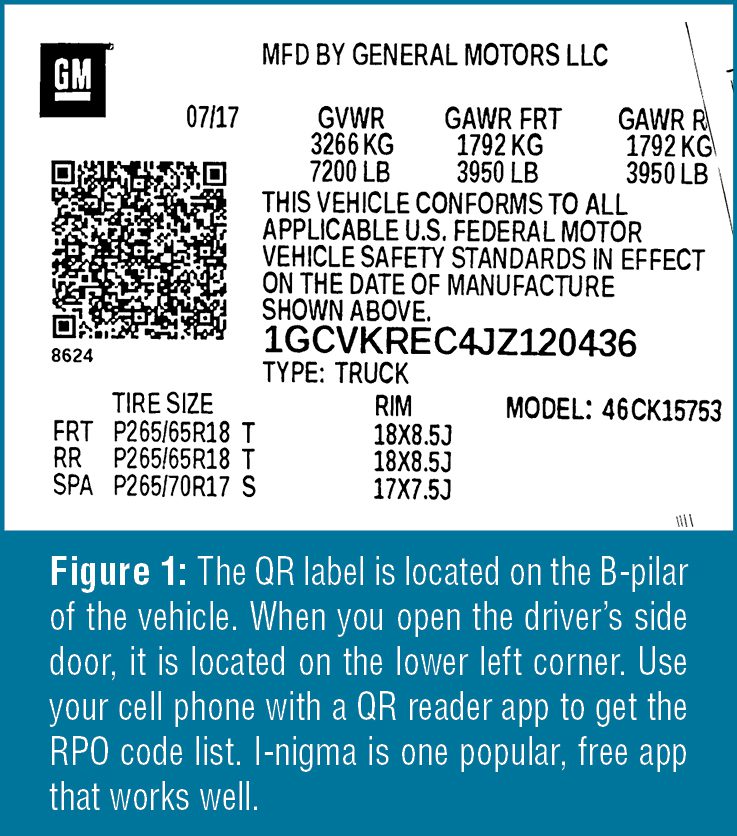
First, using the RPO code is the easiest way to identify the unit. Use your cell phone, equipped with a QR label reader app. Locate the QR label on the driver’s door B pillar, and use the phone app to display the label information (Figure 1).

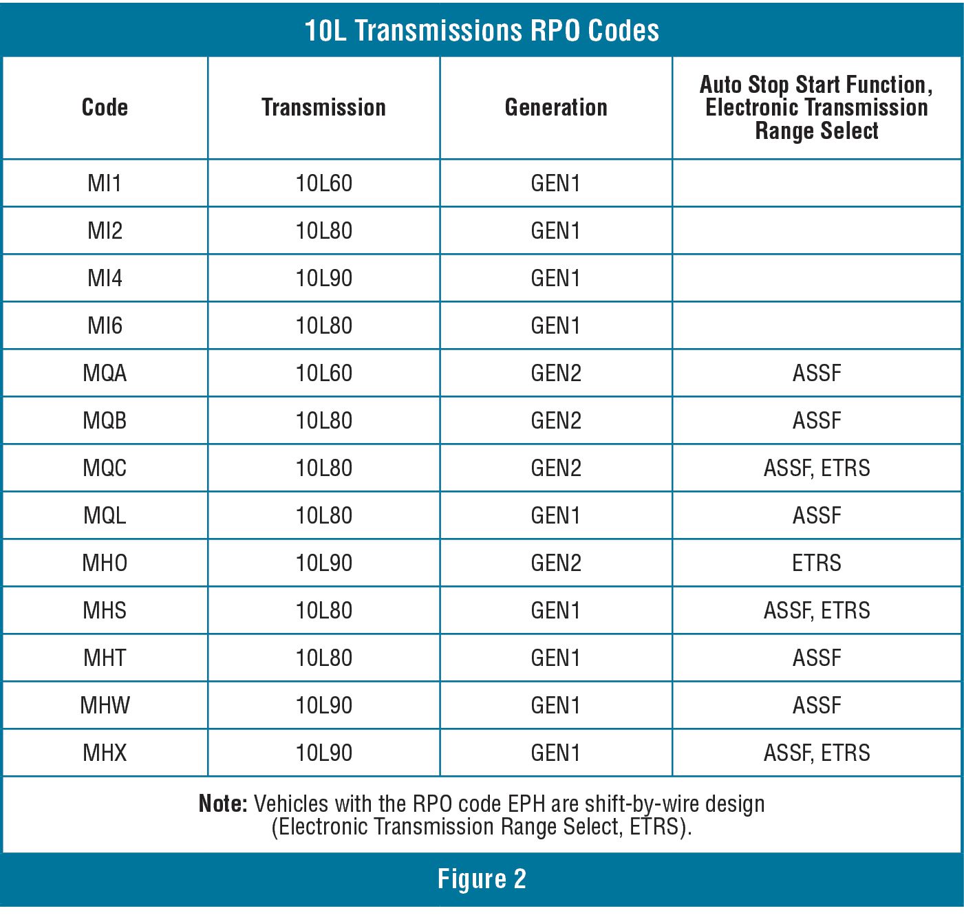
There are two versions of each transmission model available: Generation 1 and Generation 2. In addition, the transmissions are available as ETRS (Electronic Transmission Range Select) (Shift by wire) and conventional units that have a cable connecting the shifter to the transmission. Another feature available on some models is the Auto Start Stop Feature (ASSF) (Figure 2).
FAILSAFE MODES
If the TCM has no power, the transmission will be stuck in the park with high line pressure. Otherwise, the TCM program that operates the 10L uses adaptive technology to manage functional failures.
It enables the transmission to provide vehicle movement while protecting the unit from a destructive failure. As a result, there are numerous failsafe modes to keep the vehicle functional.
NO MOVE
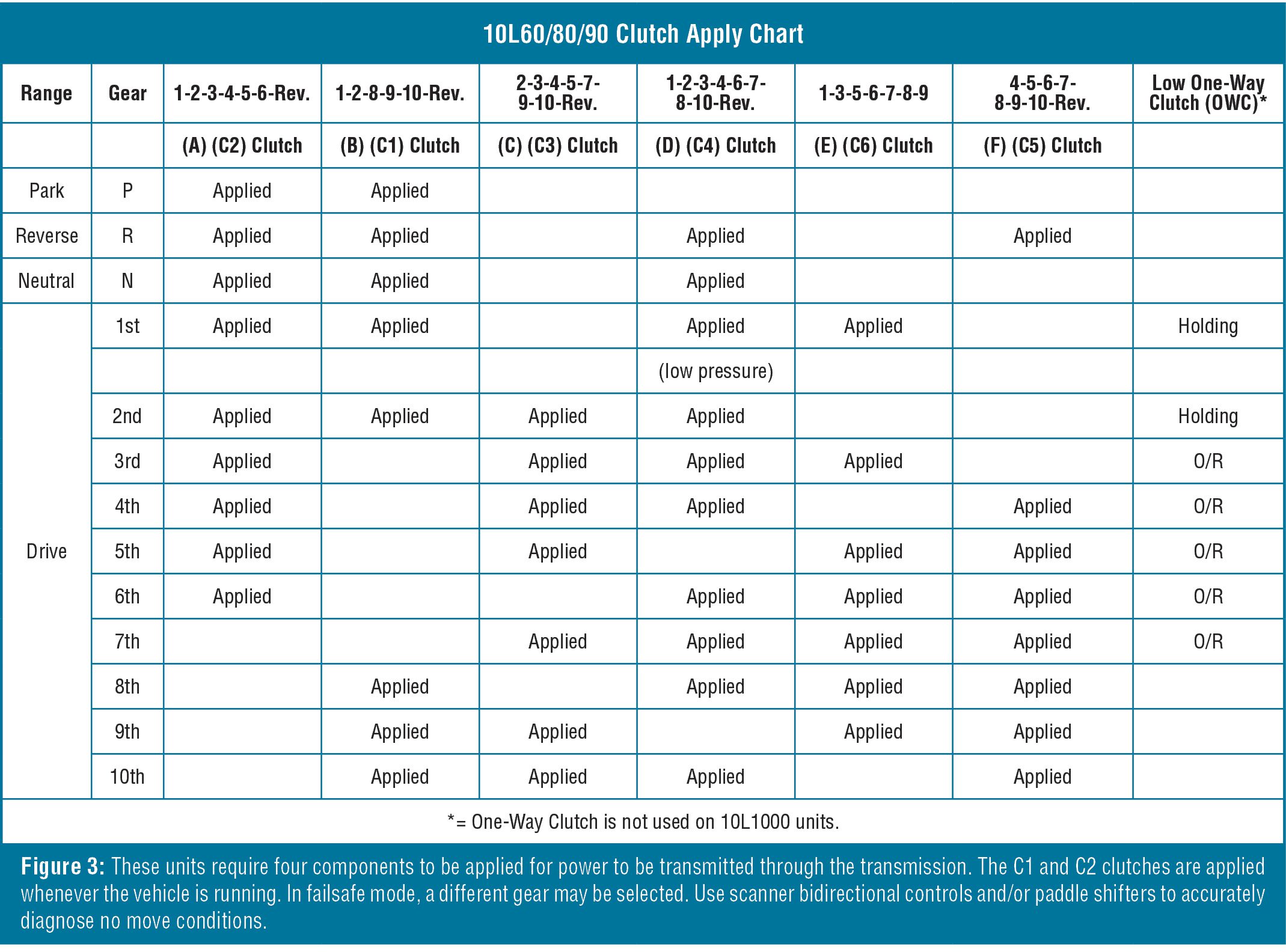
When diagnosing a no-move condition with these units, it is important to understand what is needed for power flow through the unit. Always refer to the clutch apply and solenoid apply charts (Figure 3). The 10L series transmission requires four components to be applied for power flow through the geartrain. Access your scanner’s bidirectional controls to command range changes to diagnose a no-move condition. You can manually command a second gear start using the paddle shifter for diagnostic purposes. Also, if the vehicle you are working on is a 4WD vehicle, selecting 4WD LOW will command a second-gear start, too.
NO MOVE AFTER REPAIR
Units that are shift-by-wire (RPO EPH) may have a no-move condition after the transmission was rebuilt or the valve body was serviced.

The valve body may not have been installed correctly. DTCs may be set, including P187E and/or P18AB. This is due to missing or not engaging the park pawl actuator piston. To correct the issue, use the following instructions (Figures 4a, b, and c):
- Place the park pawl actuator lever in the park position, fully forward position.
- The piston servo opening must be positioned with the slot in the vertical position as shown. Use an appropriate tool to reposition if necessary.
- Carefully place the valve body into the transmission while avoiding contact between the switch housing, magnet carrier, and the end of the park pawl actuator lever.
- Ensure the park pawl actuator lever is aligned inside the piston servo opening.
Be careful not to damage the park pawl switch or housing. When the lever is properly positioned, the valve body should drop into position without force.
SHIFT QUALITY ISSUES
Be sure to complete all the steps in your diagnostic procedure when dealing with shift quality complaints. Check for codes in all modules! Shift strategy and shift quality may be altered relative to codes stored in other modules. Unfortunately, the OEM does not always indicate symptoms directly associated with non-transmission codes. So, it is important to address them before condemning the transmission.

For example, a chassis DTC C0267 (Low Brake Fluid Level) will cause no upshifts in Tow Haul mode. The vehicle will shift correctly when Tow Haul mode is deselected. GM OEM diagnostic procedures do not indicate any connection with this code and drivability issues. Of course, a thorough inspection and repair of the brake system would be required to remedy the code.
Also, note if the vehicle has had a prior transmission-related repair. Items that will cause shift quality issues are as follows:

Incorrect clutch clearance: If clutches are outside of the specified clearance range, the transmission strategy will not be able to compensate, resulting in harsh or binding shifts.
Cooler bypass valve blocked in full bypass mode: Do not block the cooler bypass valve in full flow mode! Extended operation of the unit below the temperature range allotted for adaptive learning can cause harsh or binding shifts.
DTC P175E (Transmission Control System – Shift Limiting Active): This indicates that the TCM initiated a shift and pressure management strategy that protects the transmission due to issues detected with sensor input data on the engine or transmission control side.
HARSH SHIFT/ ENGAGEMENTS DUE TO STRATEGY
Customers may complain of shiftrelated issues, including a possible “harsh garage shift” on the first engagement after the vehicle has been sitting for a long time. These issues may be related to a standard process known as “catalytic converter lightoff” (CLO).
If the customer gets into the vehicle and immediately puts it into gear upon starting the engine, the engagement will be harsh. This issue is present no matter the transmission generation. Qualify the customer complaint with the following information before proceeding with a diagnosis.
The CLO programming commands the ECM to elevate the engine speed for about 90 seconds after starting up to raise the catalytic converter’s temperature, enabling it to function sooner. When the CLO program is active, the ECM will:
- Elevate the engine idle speed.
- Retard spark timing to raise exhaust temperature.
- Add additional fuel injector pulses.
This program will be active if the engine coolant temperature is below 158°F (70°C) during engine start-up and will remain active for 25 to 90 seconds. If the complaint occurs only within these conditions, it is considered normal.
HIGH MILEAGE ISSUES
As these units age, shift quality concerns begin. A typical customer complaint is intermittent harsh shifts. Since the TCM control strategy controls the oncoming and off-going clutch for a shift overlap of approximately 0.3 seconds, compromise within the unit due to wear is felt as a harsh shift; whether it is a flare and a bump or a binding shift, they will both feel the same.
The source of most issues tends to lie in the valve body. The root cause of concerns includes the following:
- Weak or broken solenoid retainer clips
- Sticking Linear Pintle solenoids and/or Clutch Control valves
- Worn LPC Accumulator bore
- Excessive clutch clearance
Always change or address the solenoid retaining clips when servicing the valve body. Several aftermarket solutions are available. Consult your local soft parts supplier for availability.
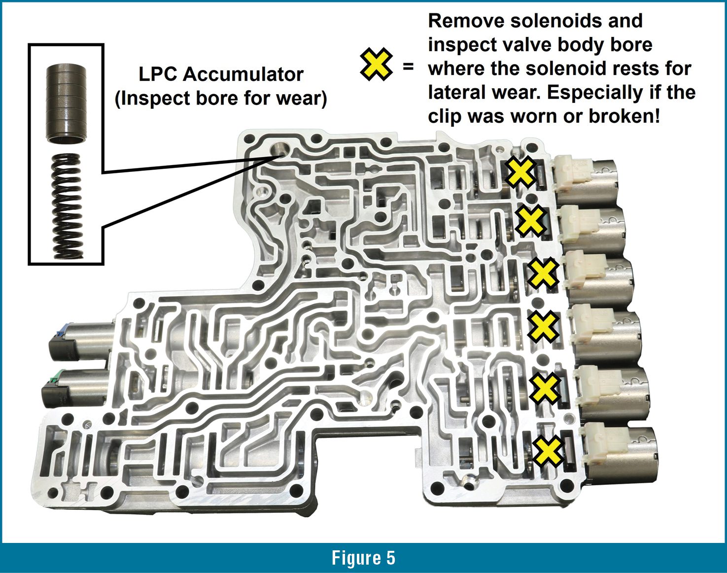
Inspect the valve body for wear in the LPC Accumulator bore and Linear Pintle solenoid bore areas (Figure 5). Note that wear in these areas requires the replacement of the valve body.
As of the publication date of this article, the Linear Pintle solenoids are not available separately. You must order a valve body and program the supplied Part Unique Number (PUN) or Mechanical Characterization and Virtual Matching (MCVM) number. You may replace a faulty solenoid with a donor solenoid; however, you must match the band number of the original solenoid.
After you have addressed all valve body-related concerns and performed the relearn procedures and are still experiencing shift quality issues, the problem is inside the unit. Clutch clearances must be within specifications for this unit to shift correctly.
Also, when you build this unit, you must replace the rotating sealing rings. Reused sealing rings will leak, causing issues with intermittent shift quality.
As technology evolves, diagnostic procedures must change and adapt accordingly. Always take time to familiarize yourself with the operating systems and characteristics of the vehicle you are working on. Here at ATRA, we are constantly researching to keep you informed on need-to-know information so you can confidently deliver the goods to your customers!