As computer-controlled vehicles age, many issues arise that can be difficult to diagnose. Some vehicles have spent harsh winters in the north being repeatedly heated and cooled to extreme temperatures, and doused with salt, water, and slush. Others have spent time in the extreme heat of the southwest deserts or the heat and added humidity of the south.
These vehicles are past factory warranty; they have an average of 100k miles and are 8 to 10 years old. Now they develop troublesome electrical issues that the engineers could never have predicted.

When the vehicle reaches your shop, it has a problem that causes the owner to believe something’s wrong with the transmission. You drive the car, experience the problem, and pull Uxxxx codes. Here’s where the fun begins.
Diagnosing CAN system problems doesn’t have to be a terrifying event. They share basic properties with most electrical systems. You can have open circuits, shorts to ground, or cross shorts.
This article provides a structured diagnostic process that’ll allow you to identify and isolate the problem and find the best resolution, without putting you at the mercy of the dealership or an electrical guru.
First, you’ll need a basic understanding of the system you’re working on. In an earlier article, we examined the basic structure of the typical CAN system (figure 1). There really isn’t much to the circuit, but you need to make sure it’s electrically stable, so it can function correctly.
BACK TO BASICS

To approach a CAN problem correctly, start by gathering as much information about the overall electrical state of the vehicle as possible.
Be a detective: Ask questions and check for recent work performed. Most CAN-related issues stem from something that was changed on the vehicle. Here’s a short list of what to look for:
- New battery, battery cables, or alternator — If the battery was disconnected, there are several systems that need to be reset or relearned. Check for aftermarket replacement components.
- Engine compartment work — Any work done under the hood should be suspect. Pay close attention to wiring harnesses, or brackets and grounds that may have been disturbed or moved.
- Added aftermarket components — These components may cause problems with the CAN system. You may need to remove or disable them before proceeding with your diagnosis.
- Recent accident or body work — Look under the vehicle for signs of major damage. Check wiring and components near the impact area. Sometimes harnesses are crushed and damage may not be obvious; you’ll need to inspect the loom closely. Don’t rule out the possibility of water damage from flooding or being partially submerged.
Also, vehicles in regions that are prone to rust may develop ground issues. Always check the battery and charging system before proceeding. Next, scan the vehicle. Use the OBD Direct, OBD Diagnose selection to access the vehicle. Don’t use the VIN ID method. When you initialize the diagnostic mode, you’ll send a wakeup call to all the modules communicating on the network.
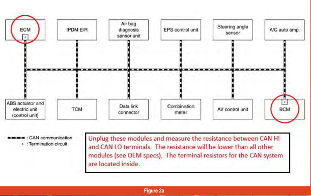
Some aftermarket scan tools will list all the modules communicating. A CAN diagram from ALLDATA, Mitchell, ShopKey, or another resource can provide a list of the modules you should expect to show up (figures 2a & 2b). If they don’t “check in,” you’ll know to investigate further.
You can also use OBD2 generic mode $9 to check for possible aftermarket module programming or wrong software levels.
If everything checks out okay on the generic side, enter the VIN ID data mode to check for parameters that may indicate a module problem, a recent reset, or a power or ground issue.
Next, check for low ignition voltage, battery disconnect, P06xx codes, or low ignition cycle counters. Always inspect the computer connectors and pins (figure 3).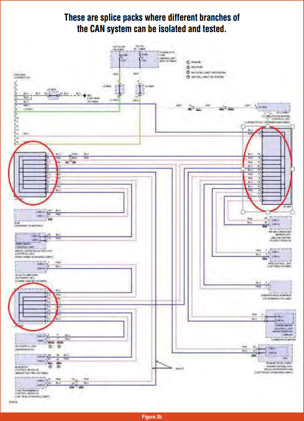
A DEEPER LOOK
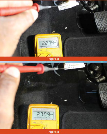
For this example, we’ll use a 2015 Nissan Sentra SV. Test CAN Hi and Low circuits, starting at the DLC. Using a DMM, graphing DMM, or oscilloscope, monitor terminals 6 and 14 using battery negative as ground reference, with the key on, engine running (KOER); (figures 4a, 4b, and 4c).
You could use a breakout box to prevent damaging the connector terminals, but, if you use micro test lead adapters and are careful, you shouldn’t have any issues.
The signal should be the same at all connected modules and splice points. If there’s no signal, check the resistance of the CAN circuit with the ignition off: Disconnect the negative battery terminal, and measure resistance across terminals 6 and 14 (CAN Hi to Low).
The resistance should be 60 ohms (plus or minus 5 ohms). Resistance higher than that may indicate poor or corroded connectors or an open circuit. Lower resistance may indicate a cross short.
Next, retrieve all returning codes. Get a computer system wiring diagram, splice pack locator, and diagnostic procedures. It may be necessary to purchase a subscription to the OEM web site to get accurate wiring diagrams and component locators specific to your vehicle. You can also contact ATRA for this.
There are three major splice packs that provide test points for diagnosis: junction connectors E2, M1, and M3 (figures 2 and 5). Check the signal at all necessary points at the splice pack and compare them to the waveform you read at the DLC.
If you find a leg that doesn’t provide the signal, disconnect the leg, see if it’s a terminal module (a module with an internal resistor), and test the resistance between the CAN Hi and Low lines.
If resistance is out of specifications, measure directly at the module. If it’s out of specification, the module is bad. If it checks correctly, the fault is between the splice pack and the module.
Resistance for a non-terminal module — one with an external resistor — should be 1 to 4 megohms; a terminal module, with the resistor built in, will measure 120 ohms (unless otherwise specified by the OEM).
Some OEM web sites offer extensive CAN breakdown information. Nissan provides specific situations for diagnosing CAN failures. The Consult 3 plus also offers more specialized testing in cases where faults lie in the modules or the embedded programming.
If all test results are okay or inconclusive, you’ll need to use an OEM scan tool to isolate the fault.
NOW, LET’S FIX IT!
CAN circuits have some unique characteristics:
- The wiring is usually a twisted pair that can be spot repaired, but if one wire needs to be replaced, you must replace the pair. They must be twisted and equal length.
- Never use a jumper wire to test a CAN system. Replace them from the module to the next node or module only.
- Never unplug a module with the ignition on or with the negative battery terminal connected.
- Avoid touching module terminals. Static discharge can damage a good module.
- It’s okay to use dielectric grease, but not too much; that could cause the female terminals to distort. Once you’ve completed repairs, you’ll need to program or initialize the modules, and vehicle systems may need to be relearned. Always take a few test drives and recheck for codes that your repairs addressed.
CAN systems are evolving every moment, but despite their complexity, they have basic foundations shared across the board. Seeing and understanding what good looks like makes it easier to identify bad. Hopefully, the next time someone asks, “Can you diagnose a CAN system?” you can say, “Yes, I CAN!”