It’s Monday morning and you already know it’s going to be one of those days, because the shop is busy, cars are everywhere, and the phone is ringing off the hook. Or maybe it’s Friday afternoon and customers are “patiently” waiting to get their cars back so they can go out of town for the holiday weekend.
If you’ve been in the transmission repair business for more than a month, you’re probably quite familiar with these scenarios and the pressure they bring with them.
This month we will be looking at pressure troubles of a different kind; the sort related to Dodge and Jeep vehicles with the RFE family of transmissions. We’ll look at how they control pressure through the pressure control solenoid, and discuss some common issues and how to troubleshoot line pressure related DTCs.
Let’s start by examining how the pressure control solenoid affects pressure on this transmission:
The TCM uses the line pressure solenoid and the line pressure sensor to control pressure in this transmission. The line pressure solenoid is a variable force-type solenoid and is an integral part of the solenoid pack.
The TCM controls the variable force solenoid by increasing or decreasing the duty cycle to obtain the pressure necessary. When duty cycle is at its lowest range (5% or solenoid off) pressure rises to maximum. When duty cycle is at its highest range (65% or solenoid on) pressure drops to minimum.

The line pressure sensor creates a signal based on the transmission line pressure, which the TCM uses to monitor that pressure.
Let’s take a closer look at line pressure control by examining a partial hydraulic diagram (figure 1). The line pressure solenoid directs oil to the end land of the pressure regulator valve. There’s no oil at the spring side of the pressure regulator valve.
This means that, when commanded duty cycle is high, more pressure reaches the pressure regulator valve through the pressure solenoid, reducing line pressure. When duty cycle is low, less pressure reaches the pressure regulator valve through the pressure solenoid, increasing line pressure.
Now let’s look at the pressure sensor (figure 2). The line pressure sensor receives a 5-volt reference signal from the TCM and a sensor ground. It provides a line pressure sensor signal to the TCM that varies in voltage based on line pressure.
When line pressure is low, the line pressure sensor signal voltage will also be low. As line pressure increases, so will the signal voltage. The line pressure sensor voltage signal should always be between 0.35 and 4.75 volts. If voltages fall outside of these parameters, it indicates a wiring issue or a faulty sensor and the TCM will set DTC P0934 or P0935.
IMPORTANT: Always refer to the factory wiring diagram for the vehicle you’re working on to avoid wire color and terminal number discrepancies.
Now that we see how pressure operates inside the transmission and how the line pressure solenoid and sensor work, we can use that to help diagnose some of the line pressure-related codes that occur with these transmissions. The diagnostic trouble codes most frequently associated with these transmissions are:
P0868 — Line Pressure Low
When Monitored: Continuously while driving in all forward gears.
Set Condition: If actual line pressure is more than 10 PSI below desired line pressure.
P0869 — Line Pressure High
When Monitored: Continuously while driving in all forward gears.
Set Condition: If actual line pressure is greater than the highest desired line pressure ever used in the current gear, while the pressure control solenoid duty cycle is at or near maximum (which should result in minimum line pressure).
P0933 — Hydraulic Pressure Sensor Range/Performance
When Monitored: Continuously with the engine running and the transmission in gear.
Set Condition: If actual line pressure is more than 172.4 kPa (25 PSI) higher than the desired line pressure, but less than the highest line pressure ever used in the current gear.
P0934 — Line Pressure Sensor Circuit Low
When Monitored: Continuously with the engine running.
Set Condition: If line pressure sensor voltage is less than or equal to 0.35 volts for 0.18 seconds.
P0935 — LINE PRESSURE SENSOR CIRCUIT HIGH
When Monitored: Continuously with the engine running.
Set Condition: If line pressure sensor voltage is greater than or equal to 4.75 volts for 0.18 seconds.
So those are the codes and their definitions. Now, how do we best diagnose them? Here’s what we know:
- When the line pressure solenoid is on (high duty cycle), line pressure should be low, and when the line pressure solenoid is off (low duty cycle), line pressure should be high.
- When line pressure is low, the sensor signal voltage should be low, and when line pressure is high, sensor signal voltage should be high.
So, when any of the line pressure-related codes set, start by checking scan data to obtain the information to help you figure out which component is causing the code.
Let’s look at the data on a scan tool taken from a 2007 Dodge Ram 5.7L with a 545RFE transmission. The scan data from this vehicle comes from a good working pickup. We’ll start with the vehicle in neutral at idle (figure 3). Desired line pressure is 124.97 PSI; pretty much identical to the line pressure of 128.97 PSI.
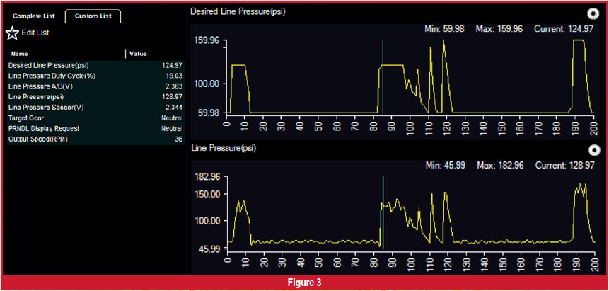
Line pressure A/D(V) or solenoid volts is 2.363V and line pressure sensor voltage of 2.344 is also almost identical, with the duty cycle at 19.03%. When looking at the scan data, notice that pressure and voltage specifications will be very similar for neutral and park.
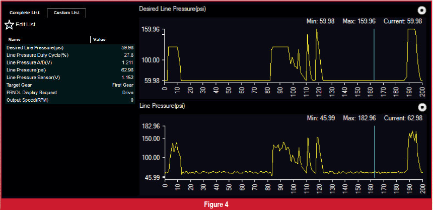
Now we’ll put it into drive, at a stop, with the engine idling (figure 4). Desired line pressure is 59.98 PSI and line pressure is 62.98 PSI, both almost the same. Line pressure A/D(V) or solenoid volts is 1.211V and line pressure sensor voltage is 1.152, both very similar, with the duty cycle at 27.8%.
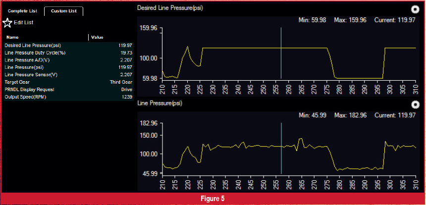
Let’s take it for a ride, with the transmission in drive, 3rd gear, and an output speed of 1239 RPM (figure 5). The desired line pressure is 119.97 PSI; same as the line pressure. Line pressure A/D(V) or solenoid volts is 2.207V and line pressure sensor voltage is also 2.207, with the duty cycle at 19.73%.
When looking at scan data during a road test, you may see desired line pressure and line pressure higher than 119.97 PSI or lower than 59.98 PSI. This could be normal operation during certain driving conditions. Check your scan data for variance between the PIDS; that’s where you’ll pick up issues and problems.
So we know that desired line pressure and line pressure should be equal, and line pressure solenoid voltage and line pressure sensor voltage should be equal. That knowledge should make for quick work with a scan tool when one of these vehicles comes in with an issue.
What happens if there are line pressure codes stored, but all of the scan data appears to be normal? In that case, the problem is intermittent, and that can make it difficult to locate the problem using live data. In that case, your best chance of finding the problem would be to take a movie when the code sets. Then you can view that data and resolve potential problems using what you know about the relationships between the pressure and signals.
One of the most common issues with these units involves the connector wiring and the pins in the line pressure sensor connector (figure 6). Very often, the solder and crimp where the wire contacts the terminal pin is faulty.
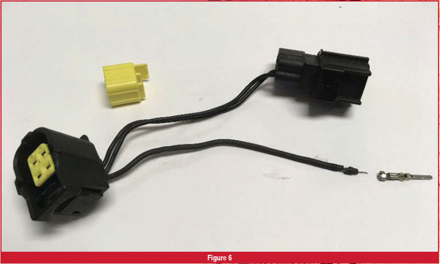
Whenever you’re dealing with intermittent codes or pressure issues on these vehicles, inspect the line pressure sensor harness and connector. A little light tugging on the wires will likely reveal these problems. A little solder repair and crimping will go a long way toward correcting them.
If needed, use the proper wiring diagram and wire in a new connector. They’re available from many different aftermarket sources.
We’ve been through the function of the line pressure solenoid, looked at scan data to reveal normal readings, and located the most common source for intermittent issues on these vehicles. With this newfound information, you should be able to correct these line pressure issues quickly and efficiently and work toward keeping these cars where they belong: on the road.