The UA80E first showed up in 2017. It was used from 2017 through 2022 in the Toyota Highlander with 2.5L and 3.5L engines. From 2018 through 2022, it came in the Toyota Camry 3.5L and Rav 4 with a 2.5L all-wheel-drive model. From 2019 through 2022, it came in the Toyota Avalon 3.5L and the Lexus ES300. And finally, you’ll find it in the 2020 Toyota Sienna with the 3.5L engine.
VALVE BODY REMOVAL AND SOLENOID IDENTIFICATION

The valve body must be removed to service the solenoids. Remove the nine bolts marked with an X, then remove the valve body (Figure 1). With the valve body off and on the workbench, remove the three bolts from the solenoid plate, remove the eight solenoids, and set them off to the side. A good habit with today’s transmissions is to mark each solenoid in order or place them in a valve body tray so you put them back in their original bore. You might consider marking them as you see in Figure 10; a simple scratch with a scribe will do. Regardless of your method, it’s a good habit so you don’t have an oopsie one day when you realize each solenoid is calibrated for that particular bore, and you have no idea where they go. Okay, back to the teardown.


Remove the one bolt from the lower side of the valve body marked with the letter A. Flip over the valve body and remove the 19 bolts marked with B & C (Figure 2). Carefully lift the upper valve body off the middle valve body. CAUTION! There are several relief and check valves under the lower valve body cover. Without micromanaging your work, you’ll be left with the upper image of Figure three. Take a moment to secure any check valves you’ve removed. There are about to be a lot more of them, and you’ll want to keep your mind clear on which parts belong in each valve body section.
Back at that upper image in figure three: notice the four bolts labeled “A.” Remove these four bolts and carefully lift the middle valve body off the lower valve body. NOTE: The plate and valve body will “spring” up because of tension on the check valves in the lower valve body. This is normal.
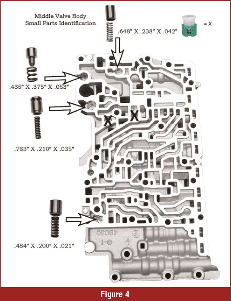
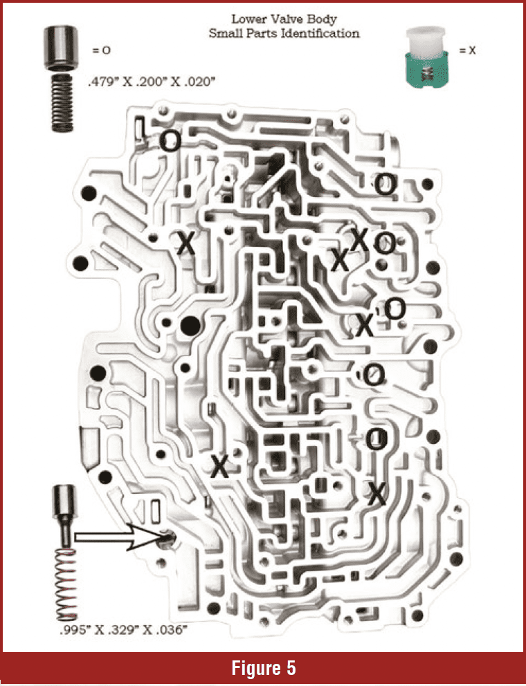
 Remove the middle valve body and separator plate and note the locations of the small parts (Figure 4). You also have a separator plate for the lower valve body to remove, with more check valves and small parts (Figure 5). Take the time now to look at each and every part. Put them back in their location and pay attention to where they go. Compare your valve body to the illustrations in the article. It’s common for some manufacturers – especially Toyota – to make minor changes to their valve bodies based on the year and model. Sometimes they’re so subtle that you may not notice the difference until it’s time to put the valve body back together. If you see this, make a copy of the images in the article and make notes on these changes now so you have it when you’re ready to go back together.

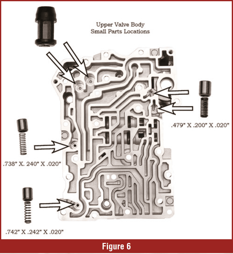
An 8mm bolt (not illustrated) secures a plate to the upper valve body. Pay attention to the small parts’ locations (Figure 6). And like before, make sure your valve body is just like the illustration. If you see a difference, make a note to get them back in their proper location. We have broken down the valve body into three sections and know where all the check valves, relief valves, and filters go. Whether you’re using a valve body tray or another method to separate and organize these parts, take the time to store them somewhere safe. The last thing you want now is to accidentally bump the tray or spill the parts, leaving you with measuring every spring to get them back to their proper location. The illustrations include the spring dimensions, but we can’t guarantee that Toyota didn’t make subtle changes to certain models. The dimensions here are what I observed and documented for the article.
Let’s move on to Removing and cleaning the valves from the upper valve body.
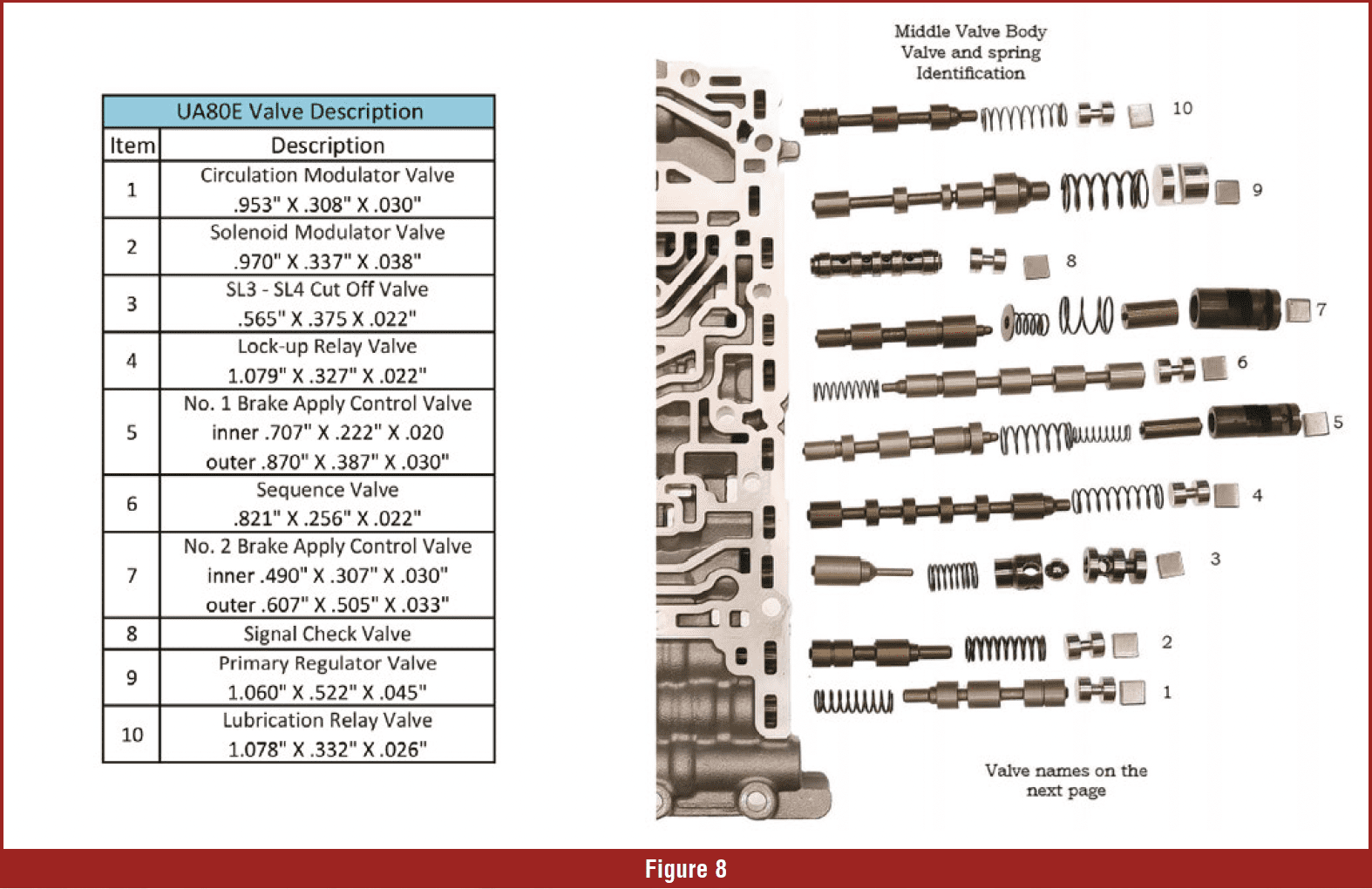
Figure seven shows the upper valve body valve, along with two of it’s valve assemblies. Check these valves for wear & grooves. If the valves are damaged, the valve body must be replaced. CAUTION! DO NOT use abrasives on the valves. Remove and clean valves in the middle valve body (Figure 8). Here again, use an abundance of caution to compare your valve body with the illustration. Also, notice the chart in figure eight, which has the spring dimensions. By now, you may be onto your fourth valve body tray, but it’s well worth the time and trouble to carefully organize these valves and components. Here again, if you find any worn valves, you’re in for a valve body replacement. To date, we haven’t seen any aftermarket repairs for known valve wear. Take a deep breath; we’re almost finished.

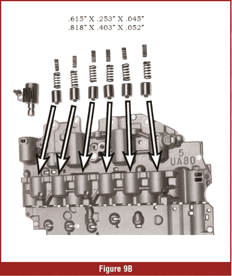
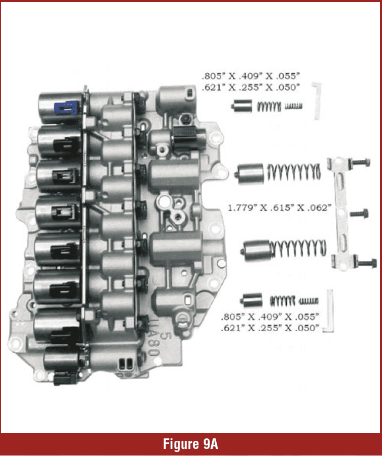
Remove and clean the accumulator pistons from the upper valve body. Check for wear & grooves in the pistons (Figures 9A & B). The springs for the pistons are all the same (each has a small and large spring), so you don’t need to be too careful about how you store the parts. You also have the spring dimensions.
After cleaning the valve body and inspecting it for wear, it’s time to go back together. Remember that single 8mm bolt that held the separator plate to the upper valve body? After installing the filters and small parts to that valve body, torque the bolt to 40 lb.
For the rest of the assembly process, just follow the reverse order. Even though you’ve carefully organized and secured your valves and springs, take the time to reference the illustrations, including the spring dimensions. Make sure you lubricate the valves and assure they move freely in their bores. You’ve already checked the valves for scoring but this isn’t the time to rush. All of the valve body bolts have a torque of 80 in. lb.
 Install the four accumulator pistons and springs shown in Figure 9a. Two of the accumulators use a retainer and the other two use a holding plate. Torque those bolts to 62 in. lb. Now install the six accumulator pistons, along with their springs, as shown in figure 9b. The seven bolts for their holding plate also have a torque of 62 in. lb. Install the solenoids in their proper bore, as you marked them during the disassembly (Figure 10). Torque these three holding plate bolts to 62 in. lb. too. Notice the chart in Figure 10 also identifies each solenoid. This may come in handy for diagnostic purposes, especially if you call the ATRA Hotline with a shift complaint, so keep the chart handy. Another idea is to save this article as a PDF and include it in your personal vault in your VTS account. It’s a great way to keep special files and notes in a transmission-specific organizer. If you’re an ATRA member and don’t know about this, give us a call and an agent will walk you through the setup. The beauty is that every person in the shop can have their own personal vault that is organized just for them. It keeps your notes and files organized as you prefer and prevents others from making any changes. If you’re not an ATRA member, then the personalized vault is another reason to join. Call us today.

Congratulations! You have gone through the complete valve body. You’ve taken your time and paid attention to the details. Good job.
In the next issue of GEARS, we’ll go through some driveability problems and complaints. If you want to know even more about this unit or get some personalized help, then see me at ATRA’s Powertrain Expo in Nashville October 25-29. My presentation is on Wednesday, October 25. I look forward to seeing you there.
One last thing, ATRA is working on a rebuild manual for this transmission and it’s slated to be ready by Expo. Reserve your copy now! This is sure to be a popular unit in your shop. Getting a jump on it is not just smart. That’s Street Smart! SEE YOU IN NASHVILLE.