We are bombarded by new transmissions everywhere we turn. Manufacturers are doing everything they can to gain an advantage in fuel economy and driving experience satisfaction. The transmission plays a vital role in both of these areas. That’s why there is such a variety of transmission types on the market today.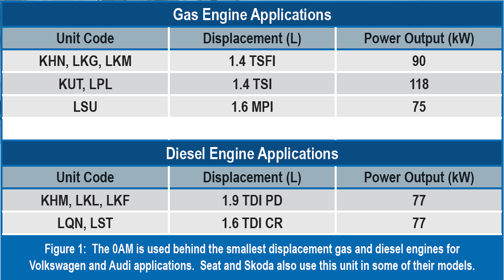
Direct Shift Gearboxes (DSG’s) are becoming a very popular choice to provide the best of both worlds. With reduced unit weight, minimal power loss through the gear train and extremely short shift timing, these transmissions are idea for small displacement engines. For more than a decade, Volkswagen has equipped numerous models with DSG’s. The 0AM transmission has been a popular unit of choice for use behind their smallest engines (figure 1).

The 0AM transmission is a 7-speed, dual dry clutch DSG. It has become a very popular unit in most parts of the world, however, it has not hit the North American markets in the same manner. The most popular application in the United States is the 0CG variant of this unit, found in the Jetta Hybrid applications. If you encounter one of these units, it is very important to understand that it is a very unique unit. Let’s take a closer look at the technology that drives this transmission.
Unit Architecture and Operation
The unit consists of two separate gear trains being driven by two separate dry clutch discs mounted in a clutch assembly. It has two input shafts and three output shafts. It uses an electromechanical assembly, called a Mechatronic, to operate the clutches and shift the internal gears. The Mechatronic assembly houses the transmission control module, sensors and actuators needed to control the transmission (figure 2). It also has its own sump, fluid and oil pump to operate the actuators. The gear train has a separate sump.
Gears 1, 3, 5 and 7 are driven by the K1 clutch which is splined to the inner input shaft. Reverse, 2nd, 4th, and 6th are driven by the K2 clutch, which is splined to the outer input shaft (figure 3). Each input shaft has its own output shaft to transmit torque to a common differential. A 3rd output shaft is used for park and reverse gear select.
When the engine is turned off, the Mechatronic commands 1st and Reverse, allowing the park lever to mechanically keep the differential from moving. Both the K1 and K2 clutches are commanded open (released) when the engine is off.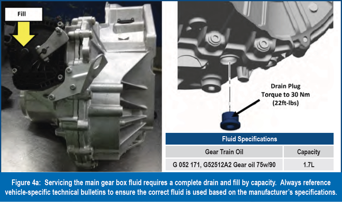
Servicing
Servicing this unit is a bit tricky. There are no level checking procedures available. The 0AM has two sumps; one for the gear box and one for the Mechatronic assembly. The 0CG variant has an additional sump for a transfer gear assembly (bevel gear). The sumps must be completely emptied and filled by the OEM specified volume (figures 4a, 4b and 4c). So, if the unit comes in with leaks, the sump would need to be drained completely and refilled by volume to the specified capacity. Always refer to OEM technical information for possible fluid specification updates.
Like any typical standard transmission, the unit must be removed to service the clutch discs. Clutch kits are available through aftermarket resources. Once the unit is removed, the vents must be plugged to prevent fluid from leaking out. Quality clutch kits will come with service plugs for this purpose.
There are two generations of clutch kits for this unit. Vehicles manufactured on or before July 2011 will use the generation 1 set up. Vehicles manufactured August 2011 and up will use generation 2. The kits are not interchangeable. Always provide the VIN to the parts supplier to assure the correct kit is used. Follow the clutch clearance set up procedure included in the kit. Failure to correctly set the K1 and K2 clutch end plays will result in clutch tie-up, flares, and/or no engagement!
Common Issues
Numerous functional and drivability issues can be resolved by updating the transmission control strategy. Even when codes exist, there may be a programming update that will address the diagnostic trouble codes in question. Common concerns related to possible programming updates are:
- Shift busyness and ‘clicking’ noise complaints
- No shifting
- Shuddering and vehicle launch concerns
- MIL illuminated (with or without storing trouble codes)
Note that some issues may be related to component failures or clutch wear. Always refer to the factory OEM site for the latest bulletins for programming updates.
Bearing noise is a common complaint for this unit. Vehicles subject to a lot of stop-and-go driving may experience lower mileage failures. During the diagnostic process, make accurate notes on when bearing noise occurs. Be specific with identifying what gear(s) and conditions the bearing noises are most pronounced. Use listening aids, like a stethoscope or electronic-assisted detection devices, to isolate bearing noise sources.
Dual mass flywheel failures are common. Complaints of clicking and/ or rattling noises may indicate that the assembly is failing. Always assess the vehicle operation for the following performance issues:
- Engine misfires
- Cylinder balance, uneven power
- Slow and/or extended engine cranking while starting
All of these items will lead to a repeat failure of the dual mass assembly. Dual mass flywheel failure tends to be more common in diesel applications. These conditions must be corrected to ensure component durability.
Inspect the dual mass flywheel teeth and retainers for damage and excessive free play (figure 5). Replace the assembly as necessary.
The Hydraulic Accumulator
Accumulator failure is the most common issue with this unit. Drivability complaints ranging from intermittent shudder on take-off to no move may indicate that this component is failing or has failed. Depending on the degree of failure, the accumulator can pose a danger if it is not handled correctly.
The accumulator is a canister that is charged with an inert gas behind a piston (figure 6). The piston is exposed to the discharge side of the pump. Oil from the pump acts on the piston filling the canister. The pump is driven by an electric motor controlled by the TCM inside the Mechatronic assembly. The TCM monitors an internal pressure sensor to maintain a pressure range between 580 and 870 psi (40-60 bar). The pressure is maintained by the opposing force of the inert gas behind the piston. The oil is used when the solenoids in the Mechatronic are commanded to operate the shift forks and clutch actuator pistons.
In the event of accumulator failure, the Mechatronic assembly can be extremely dangerous. It is necessary to handle it as if it is fully pressurized! The recommended handling procedure is as follows:
- Remove the Mechatronic assembly from the unit by removing ONLY the (7) M8 bolts securing it to the unit (see figure 7)
- Ensure you are wearing safety glasses!
- Using a titanium tipped drill bit (size unimportant), drill a hole through the Mechatronic cover into the accumulator body as shown (figure 7). Note, the drill bit needs to be long enough to penetrate approximately 2 inches into the unit.
This will release the pressure in the canister and allow you to safely remove the Mechatronic cover. The accumulator and cover are available through many non-OEM sources.
The valve body casting is usually damaged when the accumulator fails (figure 8). It is often obvious, but there may be little signs of damage unless you inspect it closely. Always check for hair line cracks and fatigue in the area where the accumulator screws into the valve body. The castings are available through aftermarket suppliers. Repair kits are also available.
As new technology enters the aftermarket, new servicing challenges usually come with it. These challenges offer opportunities for us to present solutions to the customer beyond the OEM replacement. Researching the technology will better prepare you to successfully take the vehicle efficiently from diagnosis to delivery. A little extra information can go a long way towards a smoother and safer repair process!