A faulty throttle position sensor (TPS) or accelerator pedal position sensor (APP) can cause engine or transmission issues. Hesitations, surging, hard starting and a variety of transmission shifting problems are only a few of the issues a failing TPS or APP can cause.
Although they aren’t high failure items, we do need to know how to diagnose them properly, especially when they don’t set a diagnostic trouble code.
In this issue, we’ll explore some techniques for testing potentiometers. For the remainder of this article we’ll use TP sensors to illustrate testing.
Scan Tool Testing
The first step in almost every diagnosis is to connect a scan tool to check DTCs and live data. Using live data to view TPS voltage is a good start. Most technicians are very visual people, so graphing TPS voltage allows you to take full advantage of the scan tool’s capabilities.
With the key on, engine off, observe the TPS as you move the throttle slowly from closed throttle to wide-open throttle and back again.
Then examine the graphed data for a few things: What are the minimum and maximum voltages? Do the voltages match the vehicle’s specifications? Does the signal move smoothly as you exercise the accelerator pedal? Finally, are there any dropouts in the signal voltage?
If any of these tests fail, your next step would be to test the TPS wiring before condemning the TPS.
There’s a disadvantage to this test: the refresh rate of the scan tool is too slow to catch small glitches in the signal. Because the scan tool grabs pieces of data, there are spaces between the points that the scan data screen displays. If an extremely small glitch happens to fall in between these sample points, it won’t show up on the screen.
So a gross failure will be obvious while a small or intermittent failure may not show up. These small glitches are often the cause of failures that quite often won’t set DTCs. In these cases, you may have to rely on other testing techniques.
Voltmeter Testing
Another option is to measure the TPS voltage with a voltmeter. Set the voltmeter on DC voltage and probe the TPS signal wire with the positive lead. Connect the negative lead to ground. For the sake of accuracy, it’s always a good idea to use the TPS ground wire itself since this is where the TPS gets its ground.
If the PCM is accessible, it’s always a good idea to make connections there instead of the TPS itself. This will allow you to test the wiring and connections at the same time as the sensor. Then perform the key on, engine off throttle sweep, just as you did with the scan tool.
In the case of a voltmeter test, you’re looking for the same things you did with the scan tool. How low and high do the voltages go and are there any dropouts?
Again, there are drawbacks to this test: Because the voltmeter’s sampling is also relatively slow, it may also miss some of the small dropouts just like the scan tool.
To increase the voltmeter’s sensitivity, you may want to turn the Min/Max feature on if your voltmeter is equipped with it. That will increase the sampling rate of the test and may provide better results. If your meter has a peak Min-Max feature, that will increase the sampling rate even further.
Both techniques, scan data graphing and voltmeter testing, can easily show you a serious failure but may not reveal those pesky intermittent issues. Let’s move on to the most effective technique for testing potentiometers: oscilloscope testing.
Oscilloscope Testing
A digital storage oscilloscope (DSO) is the best choice for testing. Most DSO’s sample rates are extremely fast and will be able to catch all the little glitches that the previous tests may miss.
Connect the DSO exactly the same way you did the voltmeter. Most TPSs are a 0-to-5 volt signal, so set the DSO with 0 volts near the bottom of the screen and 5 volts near the top.
Be sure to use the real estate of your DSO screen; that is, make the TPS signal fill the entire screen to make analysis easier. Set the time base relatively slow since the TPS isn’t a fast signal like a fuel injector or a crankshaft position sensor.
An additional note on DSO setup: if your DSO has an adjustable sampling rate, be sure to turn it all the way up to its fastest setting to avoid missing any small issues. Also, if your DSO is equipped with filters, shut them off. By doing these two things, you make sure you won’t miss anything when you obtain the scope capture. If desired, you can always turn the filters back on later.
A good TPS capture should look like figure 1. This vehicle has a closed throttle voltage of 800 millivolts and a wide-open throttle voltage of about 4 volts. In addition, the transition from closed to open and back again is smooth and shows no sign of dropouts or glitches.
The next TPS capture (figure 2) is from a Chrysler that exhibited intermittent surging, unwanted shifting during light throttle, and occasional engine stalling. The PCM stored no DTCs and you could easily duplicate the problem during a test drive.
The closed and open voltages matched this vehicle’s specifications but notice the glitch in both the ascending and descending portions of the signal. This is the bad spot that was causing all of the customer’s issues.
The next vehicle is another example of an intermittent issue that wasn’t setting DTCs. In this case, the technician made the connections at the PCM connector. Figure 3 shows dropouts almost all the way to 0 volts.
On this vehicle the TPS wasn’t the fault, but the TPS signal definitely had an issue. Poor connections at the TPS were causing loss of signal to the PCM. The technician checked the pin tension at the TPS connector and found it loose. He replaced the female pins inside the connector, which resolved the issue.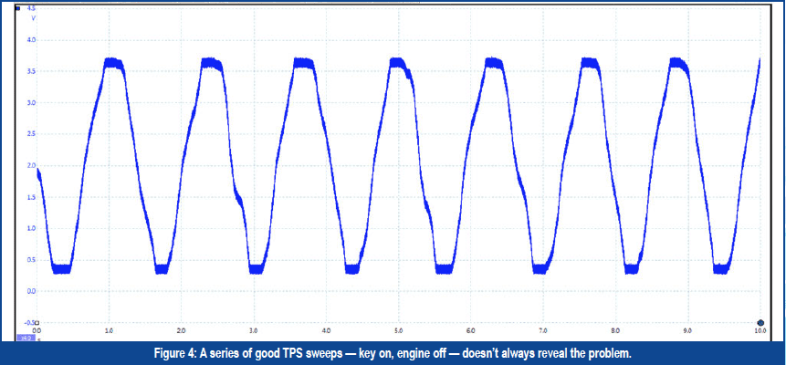
There are two things you should know about this capture: First, a voltmeter set on Min/Max would have probably caught this issue too. Second, backprobing the TPS connector could have temporarily “fixed” this issue and the TPS would have tested good on the DSO. This is why testing at the PCM connector is a good idea whenever possible.
The last vehicle is a 2001 Dodge Ram 2500 with a 5.9-liter Cummins diesel engine. The customer’s complaint is erratic shifts between gears at cruising speed and the MIL comes on.
During testing, the technician retrieved a P0122 APP. The technician replaced the APP and the problem still existed. Then he scoped the APP at the ECM connector, and performed several key on, engine off throttle sweeps (figure 4): no issues appeared.
The technician started the engine, and opened and closed the throttle again (figure 5). Obviously he couldn’t open the throttle all the way with the engine running and the vehicle in park, but you can still see an issue in the DSO capture. This is noise or electrical interference. The problem is something that causes interference only when the vehicle’s running.
Ignition systems are often to blame for unwanted interference, but we can take that off the table because this vehicle, being a diesel, doesn’t have an ignition system.
The alternator, on the other hand, could be an issue. So the technician moved the DSO leads to the alternator and changed the settings to AC voltage. The alternator ripple reached almost 1 volt (figure 6).
On this RAM, the alternator was causing the interference due to bad rectifier diodes. The technician replaced the alternator and all the issues disappeared.
As you can see, we have multiple choices for testing TP and APP sensors. All of them have some value, but using a scope is always going to be your best option. The small glitches, dropouts, and interference that cause some of our “hair-pulling moments” become easy to see using proper oscilloscope testing techniques.
Do you have any engine or electrical diagnostic issues you’d like to see addressed in the future? Let Scott know. Send him an email at scott@driveabilityguys.com and you just may have your question covered in a future issue of GEARS Magazine.