
Like many of you, I’m far from a fan of most CVTs. I guess I’m just set in my ways but I often wonder if people really test drive CVT-equipped vehicles prior to purchasing them.
But, like other things in life, the CVT is evolving. The progression over the last couple of years from some of the manufacturers has been impressive, to say the least. Subaru and now GM have developed units that truly mirror the operation and driveability of conventional automatic transmissions.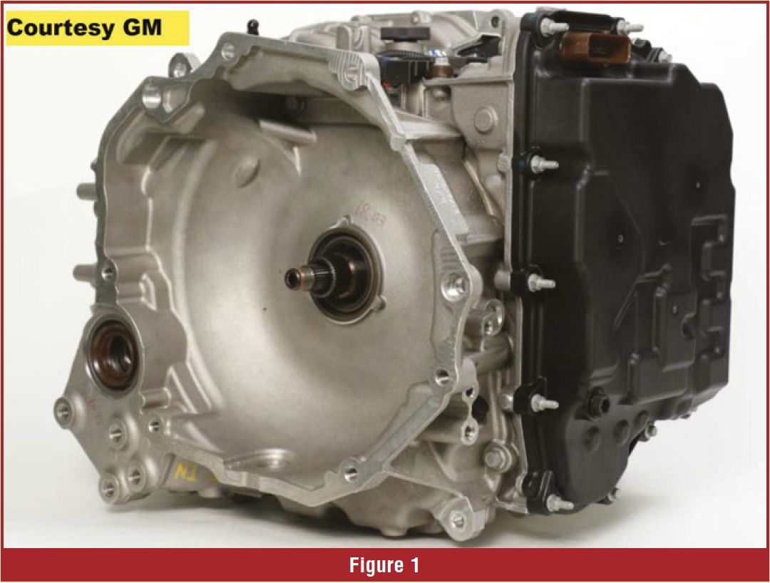
Most of you remember the GM VT20 and VT25 from many years ago. Engineers at the time took the position that GM would never build another CVT. But never say never.
New for 2019, the VT40/CVT-250 (RPO MRD) (figure 1), was introduced in the Chevrolet Malibu with a 1.5 L (RPO LVF) turbocharged engine. Most customers will have a difficult time differentiating its operation from a conventional automatic transmission.
The programming for this unit is very good. The transmission is extremely responsive to throttle input and its up/down shift patterns and shift feel are very similar to a conventional transmission. Unlike most other CVTs, the VT40 allows the engine to operate in an RPM range you’d expect from a non-CVT.
With seven speeds and a TCC, the fuel economy is excellent: I drove one for over a week and averaged 40+ MPG on the highway. City driving is also good, even though the programming will enable the TCC at around 12 MPH if you’re operating at extremely light throttle. As soon as you even look at the accelerator pedal, the unit will disengage the converter clutch and downshift to a lower ratio, just as you’d expect.
The VT40 is a single-speed (forward and reverse) unit that’s equipped with a torque converter and a TCC. The transmission uses a forward and a reverse clutch to control direction. It uses a CVT chain, rather than a belt as most other applications use (figure 2).
The hydraulic system uses multiple solenoids, valves, and a chain-driven, vane-style oil pump to control the operation of the pulleys. The system pressure in this unit is much lower than most other CVTs (figure 3).
The VT40 is also equipped with a start/stop system to improve fuel economy. The start stop system uses a gerotor electric auxiliary pump to keep the clutches engaged when the engine turns off at a stop. Like other start/stop systems, it’s an extremely annoying feature, as you can’t turn it off.
CLUTCHES
The transmission uses two clutches: a forward clutch and a reverse clutch. The forward clutch houses the input shaft and reluctor for the input speed sensor. The clutch uses two friction discs, two steel plates, and a wave plate. The reverse ring gear acts as the apply plate for the clutch and is splined to the forward clutch housing.
The reverse clutch is housed and splined to the case. A snap ring retains the reverse piston in the case, similar to various low/reverse clutches in other transmissions. The reverse clutch friction discs are splined to the reverse carrier assembly.
TCM
The TCM is a standalone unit mounted in the engine compartment area.
VALVE BODY AND SOLENOIDS
The valve body houses six, variable-force solenoids (VFS) and two fluid pressure sensors (figures 4 & 5). Solenoids 1, 2, 3, 4, and 6 are normally high (NH) designs. With this design, as current flow through the solenoid increases, solenoid pressure decreases.
Solenoid 5 is a normally low (NL) design. As solenoid current flow increases solenoid pressure increases. Like many other transmissions, the solenoids as well as the electrical components have several names, depending on the service or parts information you’re referencing. Like the 8-, 9-, and 10-speed GM units, the VT40 will require TCM reprogramming if you replace the valve body or the transmission.
The valve body also houses two pressure sensors (sensor 1 B12BA and sensor 2 B12BB) mounted to the top of the body. The pressure sensors are inputs to the TCM to provide drive and driven variator pressures. Fluid pressure sensor 1 monitors the drive pulley pressure while pressure sensor 2 monitors the driven pulley pressure. Figure 6 shows the normal pressure ranges they operate at. The sensors are 5-volt, 3-wire design.
The valve body houses 10 valves:
- Manual Valve
- Clutch Regulator
- Default Override
- TCC Control
- TCC
- Pressure Regulator and Shuttle Valves
- Variable Driven Pulley Regulator
- Variable Drive Pulley Regulator
- TCC Regulator
- Feed Limit
SENSORS
Speed Sensors (B14A, B14C, B14D) — Three speed sensors are used: input, intermediate, and output. All of the sensors are 2-wire, Hall Effect design. All of the sensors receive 9V from the TCM and develop a square wave output of about 1.5 volts.
Input (B14C) — Mounted under the valve body. The signal is developed from 60 slots in the forward clutch drum reluctor.
Intermediate (B14D) — Mounted externally on the back of the case. The signal is developed from the 45 teeth on the primary pulley reluctor.
Output (B14A) — Mounted internally in the final drive area. The signal is developed from the 53 teeth on the transfer gear.
Range Sensor (IMS) (B303) — The range sensor (IMS) is mounted inside the unit. It provides a duty cycle output based on the range selected. You can read this value with your scan tool.
Temperature Sensor (B13) — Like other transmissions, this is an NTC thermistor. The sensor is part of the transmission wiring harness.
SCAN DIAGNOSIS
A lot of scan information is available for this unit. While using the GM GDS2, you can monitor 52 separate parameters. Like other applications, output override controls are also available. ‘Service on this unit is still an unknown as it is currently serviced only by exchange. As many of you are discovering, a CVT is a very simple unit to work on. This unit also appears that it’ll be repair friendly.
Until next time, remember: “Good, Better, Best. Never let it rest until your good is better and your better is best.”


