In the May issue of GEARS Magazine, we looked at the 845RE and how it gets eight speeds out of four planets.  We discussed how the different planets were driven by different components.
In this installment of Fun with Transmissions, we’ll look at how easily this unit comes apart and the tools you’ll need to avoid breaking any parts: a real concern on these units.
Once you have the unit on the bench, breaking it down is fairly straightforward. It’s the internals you need to be careful with.
The first thing you’ll notice is the pan is plastic, with the filter and magnets built into it (figure 1). The filter isn’t replaceable separately; you’ll have to replace the pan assembly each time you service the unit.
 The pan is available through the aftermarket, but it may be a day or two away. Check your local parts supplier; they may have them in stock at a reasonable price. The good news about the plastic pan is that they fit all the rearwheel drive 8-speeds made by ZF and Dodge.
Before you can remove the Mechatronic, you’ll need to remove the pass-thru electrical connector: First remove the valve body bolt and lift the gate (Figure 2 & 3). This can be challenging because the connector has two large O-rings and a multi-lip inner seal.
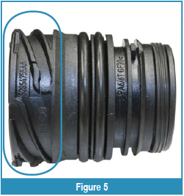
Never try to remove this pass-thru connector with pliers: It’ll destroy the connector straightaway. Instead, there’s a tool available on line — P/N 10377A — for about $40 to $50 (figure 4). The tool fits into the connector grooves (figure 5 & 6) and has enough meat on it to let you get a screwdriver between the tool and the case to pry it out.


After you have the valve body out of the transmission, stand the unit up to remove the pump and internal components. If you have a hole in your bench, you can set it upright there; if not, an old Allison tail housing works great (figure 7). It’s best to keep the unit upright because the internal parts are fragile and can distort easily while lying on its side.


Pump Removal and Disassembly
Removing the pump is a snap: Start by removing the retaining bolts. These are magnesium, torque-to-yield bolts, so you’ll need to replace them after each use Figure 8 & 9). For more, check out Steve Garrett’s article in the April 2017 issue of GEARS.
Once you have the bolts removed, pry the pump out carefully, as shown (figure 10). Never try to pry it elsewhere on the pump; you’ll likely damage the case or the pump itself.


The pump is a chain-drive, doublestroke vane (figure 11), with two inlets A-brake and B-brake (figure 12). It’s tiny, but creates enormous volume to keep the transmission working properly.
The stator support houses the entire A clutch, and the B clutch piston and cylinder (figure 13). You’ll need to remove them before disassembling the pump. They come apart just as you’d expect; nothing out of the ordinary.
Once you have the clutches removed, you can disassemble the pump. Remove the bolts and lift the pump cover off the stator.
Use a screwdriver to pry the pump body gently out of the stator support assembly. You’ll need to lift the drive gear, chain, and pump body out as a complete assembly. Once you have the pump out, set it aside; we’ll discuss disassembling and rebuilding the pump in a later article.
Geartrain Disassembly
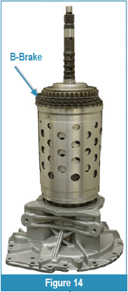
With the pump out, you can lift the entire geartrain out of the case as a complete assembly. Once again, you’ll want to set the geartrain assembly upright by sliding it into a hole in your bench, or by using a tail housing from an Allison transmission (figure 14).


First, you’ll slide off the P1 ring gear/B-clutch hub assembly. The endplay shim sits on top and will come off with it. You’ll also want to remove the thrust bearing that sits between the P1 planet and the ring gear. Set them aside for later (figure 15).
Now you’re going to remove the P4 ring gear drum snap ring. For this, you’re going to need a special reinforcing ring to protect the drum housing (figure 16). Never try to pry the ring out without the reinforcing ring in place.
The reinforcing ring kit is available through GFX (www. gfxcorp.com), part number 568999. It comes with two reinforcing rings: this one, and one you’ll need later in the rebuild. It’s a bit pricy, but worth every penny.
Before you remove the snap ring, notice its position (figure 17): The snap ring has a notch cut into it. You’ll need to reinstall it in the proper position to make sure it snaps into place.
With the reinforcing ring over the drum, pry the snap ring out of the groove. You’ll want to pry from the side opposite the snap ring opening. Once the snap ring pops out of the groove, the drum will drop slightly; this is normal.


Once you have the snap ring removed, you should see the factory support inserts that support the drum while you’re removing the snap ring. Notice their position for reinstalling them later, then remove them and lay them aside.
With the support inserts removed, you can lift the P1 planet out of the drum. Then slide the P1/P2 sun gear out (figures 18A & 18B).
Lift the input shaft/P2 planet out of the assembly. There are magnets built into the P2 planet to create the input speed sensor signal.
Remove the P2 ring gear and thrust bearing. The P2 ring gear drives the P3 sun gear, and the housing spines into the C clutch housing.
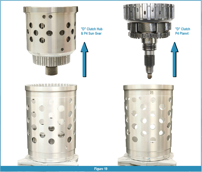
Now you can lift the D clutch hub, P4 sun gear, and C/E clutch retainer out of the housing, followed by the D clutch/P4 planet (figure 19). Both should slide right out of the housing.


To disassemble the D clutch hub, P4 sun gear, and C/E clutch, you’ll need the second reinforcing ring that came with your kit.
Notice that, like before, the snap ring is indexed and will only go in one way. To remove it, slide the reinforcing ring down over the drum and pry the snap ring from the side opposite the opening (figure 20). When the ring snaps out of the groove, the D clutch hub will drop.
Like before, there are supports for the drum to help support it while you remove the snap ring. Notice their positions and then lay them aside. With the snap ring removed, remove the P3 planet and the C/E clutch assembly from the D clutch hub (figure 21).
Remove the snap ring holding the P3 ring gear, then slide the P3 ring gear out of the drum. Now remove the second snap ring that was sitting below the P3 ring gear. From there you should be able to remove the E clutch assembly and the thrust bearing that sits below it (figure 22 & 23).
With the C clutch removed, you can remove the C clutch from the housing and the thrust bearing that sits below it.
That’s all there is to it. A lot of steps, but all fairly easy if you follow the procedures and use the proper tools. Next time we’ll look at the individual components and how to rebuild them.
Make your plans today to attend this year’s Expo, where we’ll be covering some of the more interesting aspects of the 845RE and answering your questions. This is a must-see event, so reserve your place today!